“Y” INPUTS
Switches 1 and 2 are used together to couple the input connectors. When the switches are
in their right-most position the signal + of channel 1’s input is tied to signal + of channel 2’s.
The same is true for signal -. This is useful when running in mono because only one input
cable is required to drive both channels.
It also provides a way of “daisy chaining” amps together. When using two or more amp’s,
plug the source into any input of the first amp then from the other input run a jumper to any
input on the second amp (and so on for additional amp’s).
SUB FILTERS
Switches 3 and 4 control the low frequency cut-off point. Switch 3 is for channel 1 and 4 is
for channel 2. These switches may be set separately to allow different cut-off frequencies for
each channel.
When in the left-most position, the SUB FILTER is engaged and the low frequencies are
down 3dB at 15Hz. In the right-most position the filter is disabled.
It is normal to run with the filters engaged. There is virtually no desirable audio content
below 20Hz. Any energy below 20Hz will waste the amplifier’s power and has a greater
potential for damaging speakers.
GROUND LIFT SWITCHES
Many times sound systems are connected in such a manner to cause ground loops that
result in audible hum. The purpose of switches 5 and 6 are to eliminate this ground loop. If
your system emits audible hum try moving the GROUND LIFT switches to the other position.
Each channel can be controlled independently but usually both channels will be “lifted” or
“grounded” simultaneously
GROUND LIFT switches such as the ones found in Carvin products are great for curing
ground loop problems. A more complicated and expensive way would be to isolate two
pieces of equipment from each other with ‘audio isolation’ or ‘line matching’ transformers.
However, never defeat the AC cord safety ground in any piece of electrical equipment
to open a ground loop. Doing so can damage equipment and cause serious electrical shock
or electrocution.
BRIDGE MONO
This power amplifier can be converted from stereo to mono, providing twice the power
capacity of a single channel, by switching into BRIDGE MONO mode and connecting the
speakers across the two RED binding posts.
When switches 7 and 8 are to their left-most position, the amplifier is configured for normal
STEREO operation. (If switches 1 and 2 are selected to mono it simply means both speaker
outputs contain the same program material. You would then plug one set of speakers into
channel 1’s outputs and a separate set of speakers into channel 2’s outputs. Channel 1’s
level control affects the speakers plugged into channel 1’s outputs while channel 2’s level
control affects speakers plugged into channel 2.)
When switches 7 and 8 are in their right-most position, the amplifier is setup for BRIDGE
MONO operation. This is different than standard mono mode in that channel 1’s outputs are
“out of phase” from channel 2’s. In this configuration a single set of speakers is connected
with one lead going to channel 1’s RED binding post and the other lead going to channel 2’s
10
13
Accessory Group
Recessed beneath the rear panel sits an 8 position DIP switch that controls some of the
amplifiers features. The next few paragraphs explain what the features are and how to use
them.
This is called biamping (when separating the highs and lows) or triamping (when separating
the highs, mids and lows.) The F-Series power amplifiers are well suited to this application.
The following sections illustrate a few possible configurations. By following the concepts pre-
sented here, you should be able to tailor a system to fit your needs.
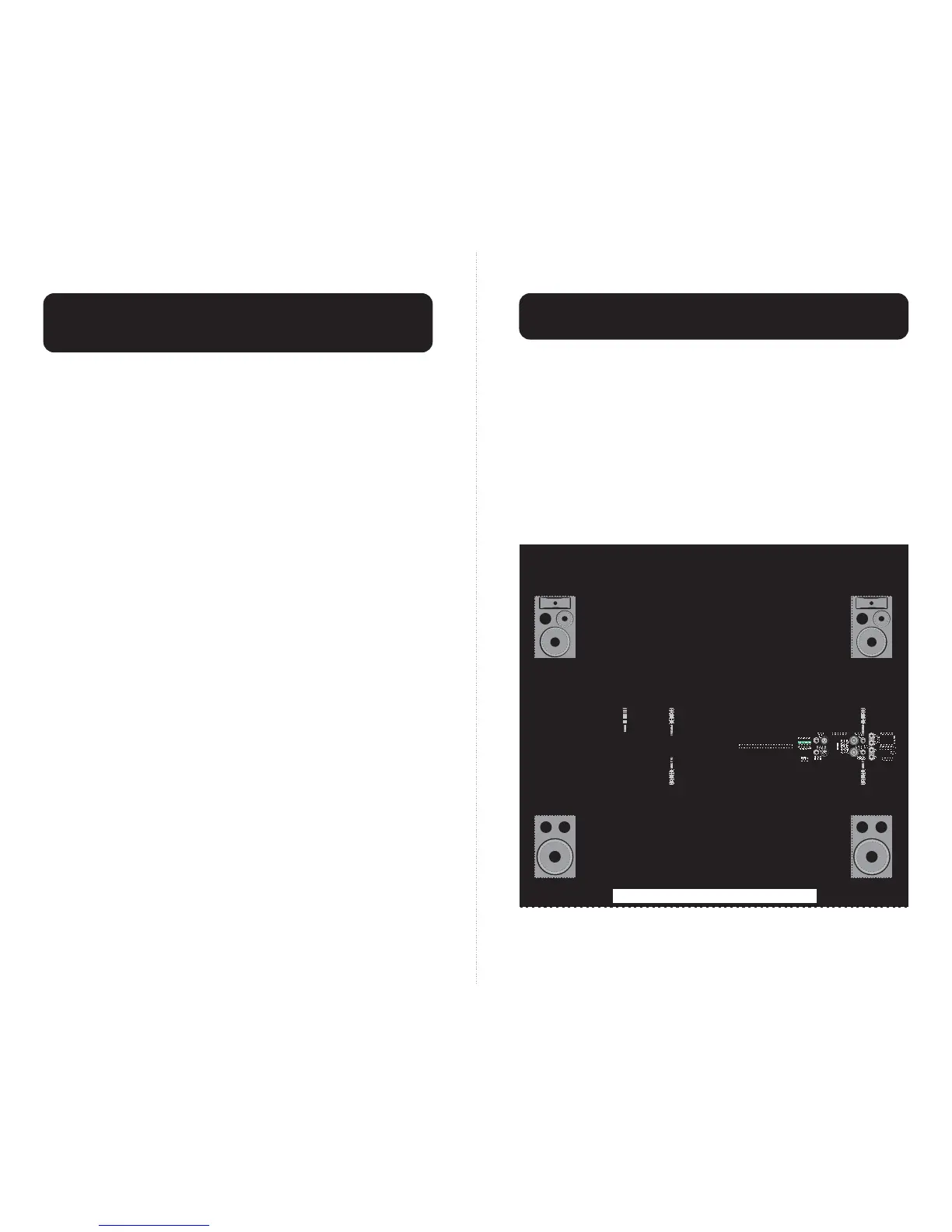
STEREO BIAMP SYSTEM
The following illustration demonstrates the use of a Carvin XC3000 active crossover, an
F1200 amplifier for lows and an F600 for highs.
By moving the speaker’s Biamp switch (if so equipped) to the Biamp position, the user is
able to feed power directly into the horn through the Hi’s input and into the woofer/mid
through the Lows input.
The crossover frequency of this setup was chosen to be 3.5kHz.
Low Amplifier
MADE
AUS
IN THE
Toll Free 1-800-854-2235
WARNING –– To prevent a fire hazard, provide adequate space for ventilation! WARNING –– To prevent fire or
shock, do not expose to rain or moisture. WARNING –– Do not remove cover. No user-serviceable parts inside.
WARNING –– Replace fuse only with same type and value.
8
MONO
BRIDGE
–
+
+
–
INPUTS OUTPUTS
PARALLEL INPUTS
GROUND LIFT CH 1
GROUND LIFT CH 2
SUB FILTER CH 1
SUB FILTER CH 2
ACCESSORY GROUP
PIN 1– : GND (–)
PIN 2+ & 2– : NOT USED
PIN 1+ : SIGNAL (+)
CAUTION: TO PREVENT SHOCK, DO
NOT DEFEAT THE SAFETY GROUND.
SPEAKER IMPEDANCE
O
H
M
S
2
BRIDGE MONO
7
6
5
4
3
2
1
RMS POWERMAX
BALANCED LINE SPEAKER
®
ON OFF
LIFT GND
STEREO MONO
STEREO MONO
120VAC 50/60Hz 1400VA
FUSE = 12A SLOW BLOW
1
2
PIN 2 : SIGNAL (+)
PIN 3 : SIGNAL (–)
PIN 1 : GROUND
1
2
PROFESSIONAL STEREO
POWER AMPLIFIER
600/600 WATTS
2 OHMS MIN. IMPEDANCE
RMS POWERMAX®[ ]
O
H
M
S
4/8
FUSE
Left
Highs
PHASE
MADE
AUS
IN THE
INPUT
XC3000
Electronic Crossover
IN
OUT
CHANNEL TWO CHANNEL ONE
LOW OUT MID OUT HIGH OUT LOW OUT MID OUT HIGH OUT LOW OUT
SUM
S/N REMOVED
INPUT
IN
OUT
IN
OUT
IN
OUT
IN
OUT
IN
OUT
PHASE PHASE PHASE PHASE PHASE
CH 1/2
50-60Hz 20VA
120V 240V
MON 1 EFF 1 EFF 2
BAL SENDS
LEFT/3 RIGHT/4 MAIN
R
POWER
L
SENDS
C
CNTRL
STEREO RETURNS
TAPE SEND
L R
B
A
MON 2
RM
LAMP
12V
SUB 1 PHONESSUB 2
Mixer Output
Crossover
Input
High Amplifier
Right
Lows
Left
Lows
Right
Highs
MADE
AUS
IN THE
Toll Free 1-800-854-2235
WARNING –– To prevent a fire hazard, provide adequate space for ventilation! WARNING –– To prevent fire or
shock, do not expose to rain or moisture. WARNING –– Do not remove cover. No user-serviceable parts inside.
WARNING –– Replace fuse only with same type and value.
8
MONO
BRIDGE
–
+
+
–
INPUTS OUTPUTS
PARALLEL INPUTS
GROUND LIFT CH 1
GROUND LIFT CH 2
SUB FILTER CH 1
SUB FILTER CH 2
ACCESSORY GROUP
PIN 1– : GND (–)
PIN 2+ & 2– : NOT USED
PIN 1+ : SIGNAL (+)
CAUTION: TO PREVENT SHOCK, DO
NOT DEFEAT THE SAFETY GROUND.
SPEAKER IMPEDANCE
O
H
M
S
2
BRIDGE MONO
7
6
5
4
3
2
1
RMS POWERMAX
BALANCED LINE SPEAKER
®
ON OFF
LIFT GND
STEREO MONO
STEREO MONO
120VAC 50/60Hz 1400VA
FUSE = 12A SLOW BLOW
1
2
PIN 2 : SIGNAL (+)
PIN 3 : SIGNAL (–)
PIN 1 : GROUND
1
2
PROFESSIONAL STEREO
POWER AMPLIFIER
600/600 WATTS
2 OHMS MIN. IMPEDANCE
RMS POWERMAX®[ ]
O
H
M
S
4/8
FUSE
 Loading...