16
REF DESCRIPTION PART # QTY
1 Circuit Card Assy. (Front Card) . . . . . . . . . . . . . . . . . . . . . . . . . . . . .80-40624-1 . . . . . . . . . . . .1
2 Circuit Card Assy. (Tube Card) . . . . . . . . . . . . . . . . . . . . . . . . . . . . .80-40624-2 . . . . . . . . . . . .1
3 Circuit Card Assy. (Rear Connect Card) . . . . . . . . . . . . . . . . . . . . . .80-40624-3 . . . . . . . . . . . .1
4 Circuit Card Assy. (A.C. Card) . . . . . . . . . . . . . . . . . . . . . . . . . . . . .80-40624-4 . . . . . . . . . . . .1
5 Circuit Card Assy. (Driver Card) . . . . . . . . . . . . . . . . . . . . . . . . . . . .80-40628-1 . . . . . . . . . . . .1
6 Circuit Card Assy. (Output Card) . . . . . . . . . . . . . . . . . . . . . . . . . . . .80-40628-2 . . . . . . . . . . . .1
7 Front Panel . . . . . . . . . . . . . . . . . . . . . . . . . . . . . . . . . . . . . . . . . . . .10-40001 . . . . . . . . . . . . .1
8 Chassis . . . . . . . . . . . . . . . . . . . . . . . . . . . . . . . . . . . . . . . . . . . . . . .10-40009 . . . . . . . . . . . . .1
9 Bracket, Fan . . . . . . . . . . . . . . . . . . . . . . . . . . . . . . . . . . . . . . . . . . .10-10017 . . . . . . . . . . . . .1
10 Heatsink, custom, natural aluminum finish . . . . . . . . . . . . . . . . . . . .12-00504 . . . . . . . . . . . . .1
11 Fan, DC 24V . . . . . . . . . . . . . . . . . . . . . . . . . . . . . . . . . . . . . . . . . . .70-02407 . . . . . . . . . . . . .1
12 Bridge Rectifier, 35A . . . . . . . . . . . . . . . . . . . . . . . . . . . . . . . . . . . . .60-35040 . . . . . . . . . . . . .1
13 Tube, 12AX7A Dual Triode . . . . . . . . . . . . . . . . . . . . . . . . . . . . . . . .65-00127 . . . . . . . . . . . . .1
14 Transformer, Power, Toroid . . . . . . . . . . . . . . . . . . . . . . . . . . . . . . .See Chart . . . . . . . . . . . . .1
15 Control Knob (Red) . . . . . . . . . . . . . . . . . . . . . . . . . . . . . . . . . . . . . .07-18012 . . . . . . . . . . . . .1
16 EQ. Fader Cap . . . . . . . . . . . . . . . . . . . . . . . . . . . . . . . . . . . . . . . . .07-70184 . . . . . . . . . . . . .1
17 Switch, Power . . . . . . . . . . . . . . . . . . . . . . . . . . . . . . . . . . . . . . . . . .25-31350 . . . . . . . . . . . . .1
18 Cover, Chassis (Not shown) . . . . . . . . . . . . . . . . . . . . . . . . . . . . . . .10-06005 . . . . . . . . . . . . .1
19 Foot, .875x.3125 (Not shown) . . . . . . . . . . . . . . . . . . . . . . . . . . . . . .03-19682 . . . . . . . . . . . . .4
20 Power Cord, AC, 16AWG (Not shown) . . . . . . . . . . . . . . . . . . . . . . .05-01604 . . . . . . . . . . . . .1
14
3
5
7
1
10
2
12
13
17
15
4
8
9
11
6
16
Fuse/Transformer Selector Chart
Model Line Fuse Value Transformer P/N
RSP.............120 VAC...............1/4A, 250V, Slow Blow . . . . . . . . .15-01000
RSP.............240 VAC...............1/8A, 250V, Slow Blow . . . . . . . . .15-01000
R600............120 VAC................6A, 250V, Slow Blow . . . . . . . . . .15-06122
R600............240 VAC................3A, 250V, Slow Blow . . . . . . . . . .15-06241
CAUTION
RISK OF ELECTRIC SHOCK
THIS UNIT CONTAINS HIGH VOLTAGE
COMPONENTS INSIDE. REFER SERVICING
TO QUALIFIED SERVICE PERSONNEL.
REPLACEMENT PARTS GUIDE
M A I N T E N A N C E
Carvin’s Red Line Series amplifiers have been designed to require very little user maintenance.
However, use caution to avoid spilling liquids or allowing any other foreign matter inside the
unit. The internal 12AX7A vacuum tube requires no routine maintenance and should last for
many years. To replace a bad tube disconnect the AC power cord from the electrical outlet and
remove the top cover. Remove the bad tube by gently wiggling it side to side while pulling up
until it comes free. Now insert a known good tube into the socket and reinstall the top cover.
The 12AX7A is a very popular tube in guitar amplifiers which any local music store should be
able to supply. Equivalent replacements for this tube are: 12AX7, 7025, and ECC83.
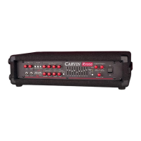
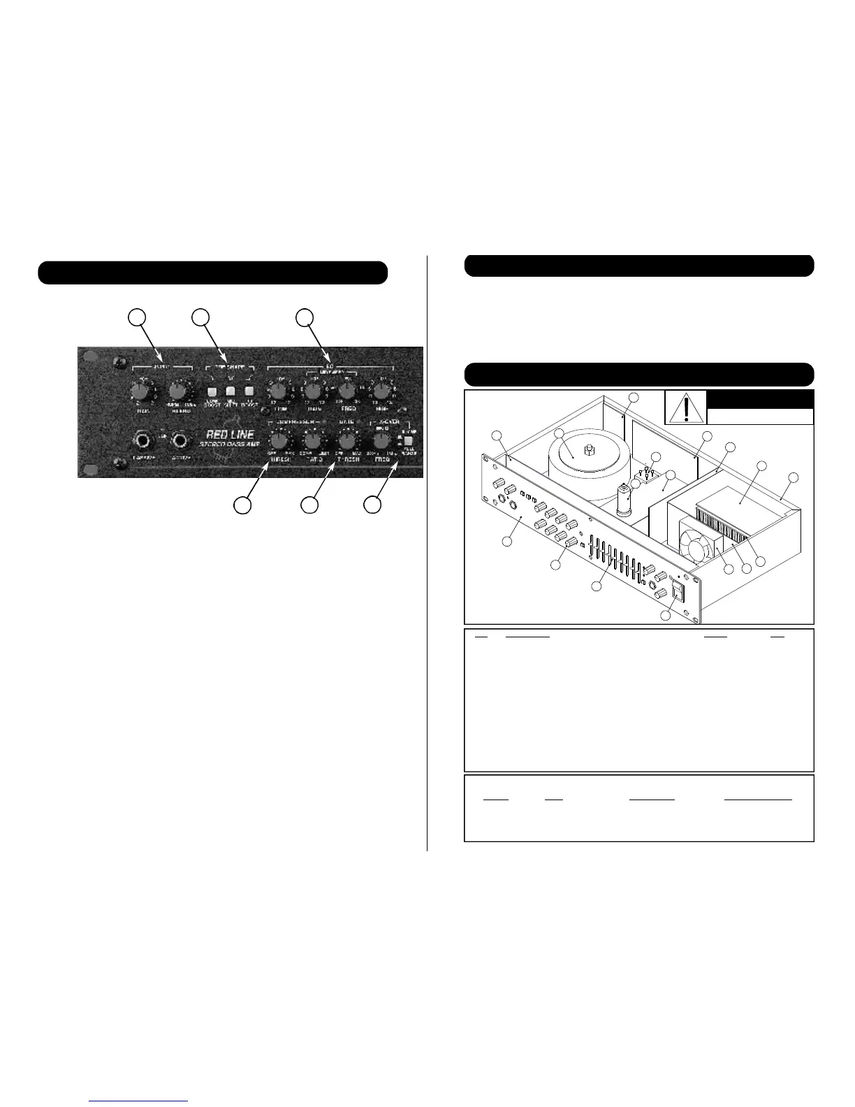
1. INPUT GROUP
Two 1/4” phone jacks are provided to accommodate both PASSIVE and ACTIVE instru-
ments. The GAIN knob is used to set the input level, and the BLEND knob controls how
much signal is mixed through the vacuum tube. The red CLIP LED indicates when the
input is close to clipping.
2. PRE SHAPE EQ.
Three bands of user selectable voicing allow quick and easy tonal changes and provide a
good starting point when setting up the eq..
3. MAIN EQ.
HIGH and LOW shelving Eq., plus a parametric style Mid provides maximum tone con-
trol.
4. COMPRESSOR
Studio quality compressor / limiter with adjustable T H R E S H O L D a n d R A T I O c o n t r o l s
and a LED to indicate when compression is taking place.
5. NOISE GATE
Integrated noise gate with input sensing and output gating, and gated indicator LED.
FRONT PANEL FEAT U R E S
3
1
2 3
6
54
 Loading...