Do you have a question about the CAS CI-1500 and is the answer not in the manual?
Highlights quality, accuracy, ease of use, 6-digit display, RFI/EMI screening, watchdog, and weight backup.
Details data storage, display rate adjustment, tare setting, self-test, and external I/O capabilities.
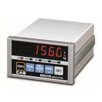
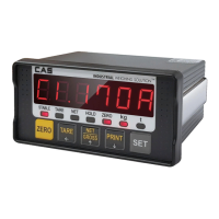
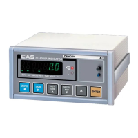
Explains the meaning of ST, TARE, NET, HOLD, and ZERO indicator lamps.
Describes the function of each key (ZERO, TARE, NET/GROSS, PRINT, SET).
Details pin assignments for load cell excitation and sense voltages, and shield.
Illustrates the typical wiring diagram for connecting a load cell.
Provides a table mapping wire colors to connector pins for various manufacturers.
Instructions on how to access the test mode by pressing the ZERO key during power-on.
Explains the role of SET key and other keys for changing values.
Describes the procedure for testing individual keys and their corresponding inputs.
Details how to perform and interpret the display test for all segments.
Explains testing of load cell input and analog-to-digital conversion.
Describes the procedure for testing RS-232C communication with a computer.
Details how to test the printer connection and functionality.
Covers testing of external inputs and outputs, specifically for CI-1560A.
Instructions on entering calibration mode via the SET key during power-on.
Explains the function of SET, ZERO, TARE, NET/GROSS, and PRINT keys.
Details setting the maximum measurable weight for the scale.
Describes setting the minimum division (resolution) of the scale.
Specifies the weight to be used during span calibration within defined limits.
Guides through the process of performing zero calibration for the scale.
Details the procedure for span calibration to ensure accuracy.
Instructions on entering set mode by pressing the TARE key during power-on.
Explains the function of SET, ZERO, TARE, NET/GROSS, and PRINT keys.
Lists various settings including display unit, serial port usage, and auto print.
Instructions on entering weighing mode via the power switch.
Describes the function of ZERO, TARE, NET/GROSS, and PRINT keys.
Demonstrates how to perform zero compensation for weight measurement.
Illustrates the step-by-step usage of the tare function for weighing.
Shows how to switch and display between NET and GROSS weight.
Demonstrates how to use the HOLD function to freeze the weight display.
Guides on printing weighing data, including total print format.
Details baud rate, output mode, data bit, stop bit, and parity settings.
Provides a C language sample code for serial communication.
Provides a BASIC language sample code for serial communication.
Wiring diagrams for connecting the indicator to a PC's serial port.
Wiring diagram for connecting the indicator to a CAS TOP printer.
Wiring diagram for connecting the indicator to a CP-7000 Series printer.
Details on connecting the serial port to the clock function.
Wiring diagram for connecting the indicator to a sub-display.
Lists and explains common errors like ERR 02, ERR 13, and OVER.
Details errors occurring during calibration, such as ERR 21, ERR 22, ERR 24, ERR 25.
| Category | Accessories |
|---|---|
| Model | CI-1500 |
| Brand | CAS |
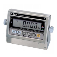
| Display Type | LCD |
| Display Digits | 6 digits |
| Power Source | AC Adapter |
| Readability | 1 g |
| Type | Compact Scale |