Home
CAS
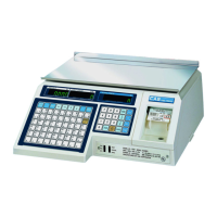
Scales
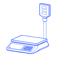
PR-II Series
Service Manual
Page 16 (4 The Schematics and Diagram)
CAS PR-II Series - 4 The Schematics and Diagram; System Block Diagram; Circuit Diagram; Interface
27 pages
Manual
To Next Page
To Next Page
To Previous Page
To Previous Page
Loading...
`
16
CAS
ELECTRICS
CO.,LTD
4. The Schemat
ics and Diagram
4
.1.
System Block D
iagram
4
.2.
Circuit Diagram
P
le
as
e
c
a
ll
y
o
ur
C
AS
d
ea
le
r
.
4.3. Interface
4.3.1. RS232C Interface (direct)
1,
4,
6,
7,
8,
9: Not connected
2: RX DA
T
A
3: TX DA
T
A
5: Ground
15
17
Table of Contents
Main Page
Default Chapter
2
Table of Contents
2
1 Introduction
3
Preface
3
Precaution
3
2 Classification
4
Overall View
4
Specifications
5
Display & Key
6
Display
6
Key Function
7
Dimension
8
Scale
8
Loadcell
9
Sealing Method
9
3 Calibration
10
Calibration Mode
10
Span Calibration
11
4 The Schematics and Diagram
16
System Block Diagram
16
Circuit Diagram
16
Interface
16
RS232C Interface (Direct)
16
USB Interface
17
5 Firmware Update Method
17
6 Exploded Views
17
7 Parts List
19
Electronic Parts
19
Mechanical Parts
22
Upper Case Ass'y
23
Tray Ass'y
23
Platform Ass'y
24
Image Ass'y
25
C/T Ass'y
26
Loadcell Parts
26
Revision
27
Other manuals for CAS PR-II Series
Owner's Manual
24 pages
Related product manuals
CAS PR Series
14 pages
CAS PR-C series
18 pages
CAS PR2-15
26 pages
CAS PDS
38 pages
CAS PD-2
15 pages
CAS PD-I
9 pages
CAS PD-II
51 pages
CAS Poscale
119 pages
CAS PB Series
20 pages
CAS PDI Series
44 pages
CAS PDN Series
28 pages
CAS LP 1.6 Series
34 pages

 Loading...