SECTION 2 - CONTROLS, INSTRUMENTS AND OPERATION
2ï91
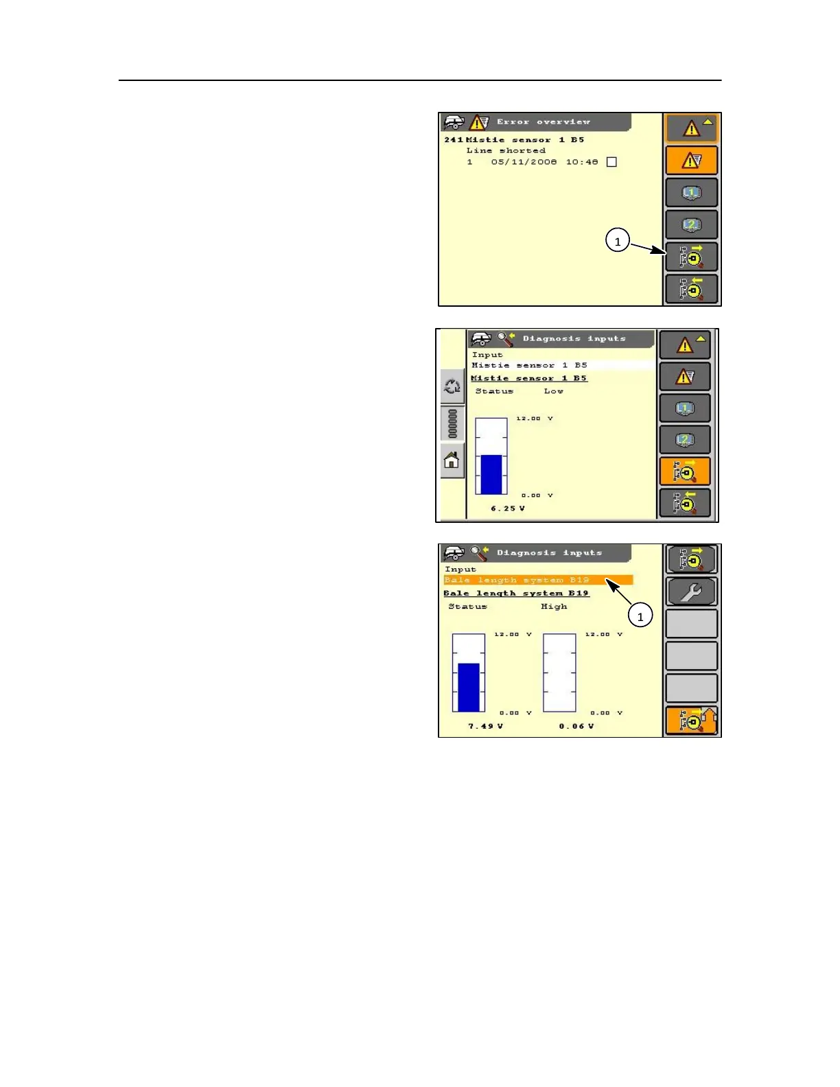
DIAGNOSIS INPUT
Inputs from sensors and other sources can be displayed,
which are used for Dealer guidance.
These can be viewed through the error overview
screen using the diagnosis input icon (1), and by use
of the soft key or touch screen.
An example of an input diagnosis is mistie sensor as
shown here where the sensor can be viewed to see if
it is okay to use or defective.
As in the case of the optional bale length system
which can be checked in the same way and
adjustments made.
Shown below is the list of inputs that can checked by
selecting the input field (1) using the key pad or rotary
encoder, touch screen:
Controller voltage
Battery voltage
10v reference voltage
8v reference voltage
5v reference voltage
Flywheel brake - B1
Mistie 1 - B5
Mistie 2 - B4
Mistie 3 - B3
Mistie 4 - B2
Mistie 5 - B6
Mistie 6 - B21
Knotter gearbox - B7 Pick-up speed -
B8 Feeder shearbolt - B9
Cutter status - B10
Bale drop - B11
Bale chute - B18
Bale length I - B19
Bale length II - B20
Needle yoke - B12
Feeder trip - B13
Knotter shield - B14
Oil pressure - B16
Loadsensor - B17
Greas
ing
senso
r -
B15
Moist
ure
senso
r -
A23