SECTION 2 - CONTROLS, INSTRUMENTS AND OPERATION
2ï4
5
The plunger moves the charge flake back and
compresses it against the bale to be formed in the
bale chamber. Both bale chamber side doors (6) and
top door (5) are hinged and can move under the
action of two density cylinders (8). This is to modify
the outlet section of the bale chamber and thus to
control the density of the bales produced. An
electronic system measures the load on the plunger
when pushing material rearwards. The electronic
system will control the hydraulic bale density system
until the load measured is the same as the density
value pre-set by the operator. That value must be
chosen in relation to the nature and to the moisture
content of the crop to be baled, as well as the bale
density required.
While the bale travels rearward in the bale chamber,
it activates bale length metering wheel (4). When the
desired bale length is reached, a mechanism will trip
knotters (3) and needles (9), which are timed with
baler plunger (1).
6
At each side of the machine, twine balls are provided.
Twine will be fed to the tucker twine arms, located
above the bale chamber, and to needles (9), located
underneath the bale chamber.
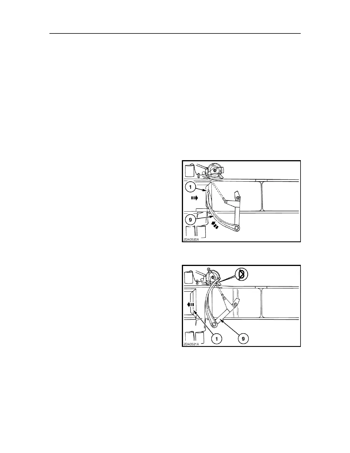
During the compression stroke of plunger (1), needles
(9) will raise towards knotters (3), bringing along the
lower twine (Fig. 6).
When the needles reach the knotters they will also
pick-up the upper twines. Both twines are laid in the
knotter (Fig. 7), tied together and the ends are cut to
finish the bale (Fig. 8).
7