SECTION 2 - CONTROLS, INSTRUMENTS AND OPERATION
2ï22
34
TRACTOR HYDRAULIC CONNECTIONS
Depending on the equipment available, the tractor may
require the following hydraulic remote controls with a
maximum pressure available of 190 bar (2760 psi).
Ensure your tractor is equipped with standard
hydraulic connectors according
to ISO 7241 (1/2 in).
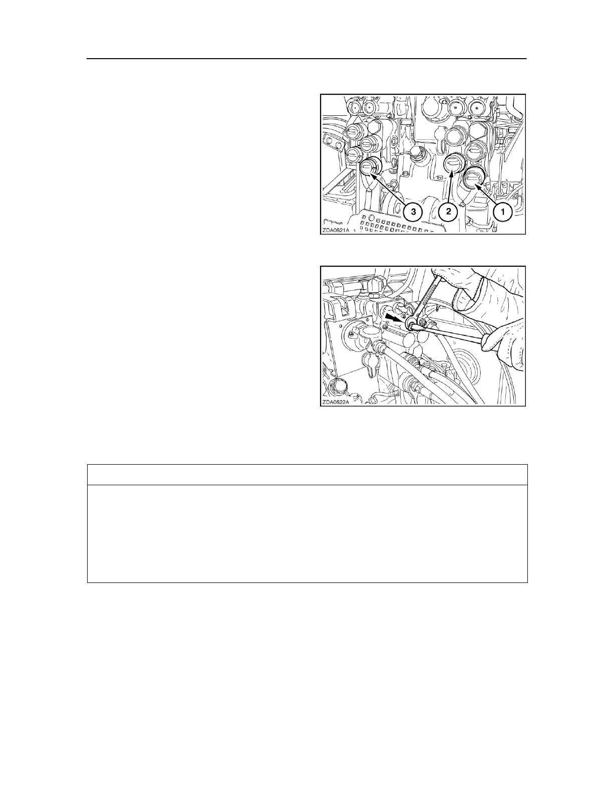
One single acting control valve (2): Pick-up.
Double acting control valve (1) Bale ejector - Bale
chute positioning system - tandem Autosteer axle.
35
Double acting control valve (3) crop cutting system.
NOTE: The double acting control valve used for bale
ejector - bale chute positioning system - tandem
Autosteer axle, should be adjusted to a kick‐off pressure
of minimum 160 bar (2320 psi) (refer to your tractor
Operator's Manual to carry out that job or contact your
local dealer).
36
The function of the hydraulic lines on the baler can be
recognized on the colour of the blanking plug.
Double acting
NOTE: if your baler is equipped with a tandem
Autosteer axle, the double acting control valve must
have a float position.
Attach the quick-coupler with the green blanking
cover to a single acting control valve for the operation
of the pick-up hydraulic circuit. Raise and lower the
pick-up several times with the tractor hydraulic
system. This will purge air from the hydraulic system
and fill the system with oil.
Attach the quick-couplers with the blue blanking
covers to a double acting control valve (with float