SECTION 2 - CONTROLS, INSTRUMENTS AND OPERATION
2ï29
Route the other, dual, cable looms inside the tractor
The cable loom with the two orange wires have to be
suitable electrical source which delivers
volts only after switching on the tractor ignition
For most tractors route the cable to the fuse box
Refer to the tractor's operator's manual
Install the monitor in a convenient location in the
cab, within reach of the operator, preferably to
the right-hand side of the tractor seat.
Connect the remaining wiring loom (with connector)
to the monitor wiring loom.
When adjusting, cleaning, lubricating or carrying out
repairs, the baler must be completely stopped.
PTO, stop the tractor engine, remove
tractor starting key, engage the baler flywheel brake
and lock the knotter tripping mechanism.
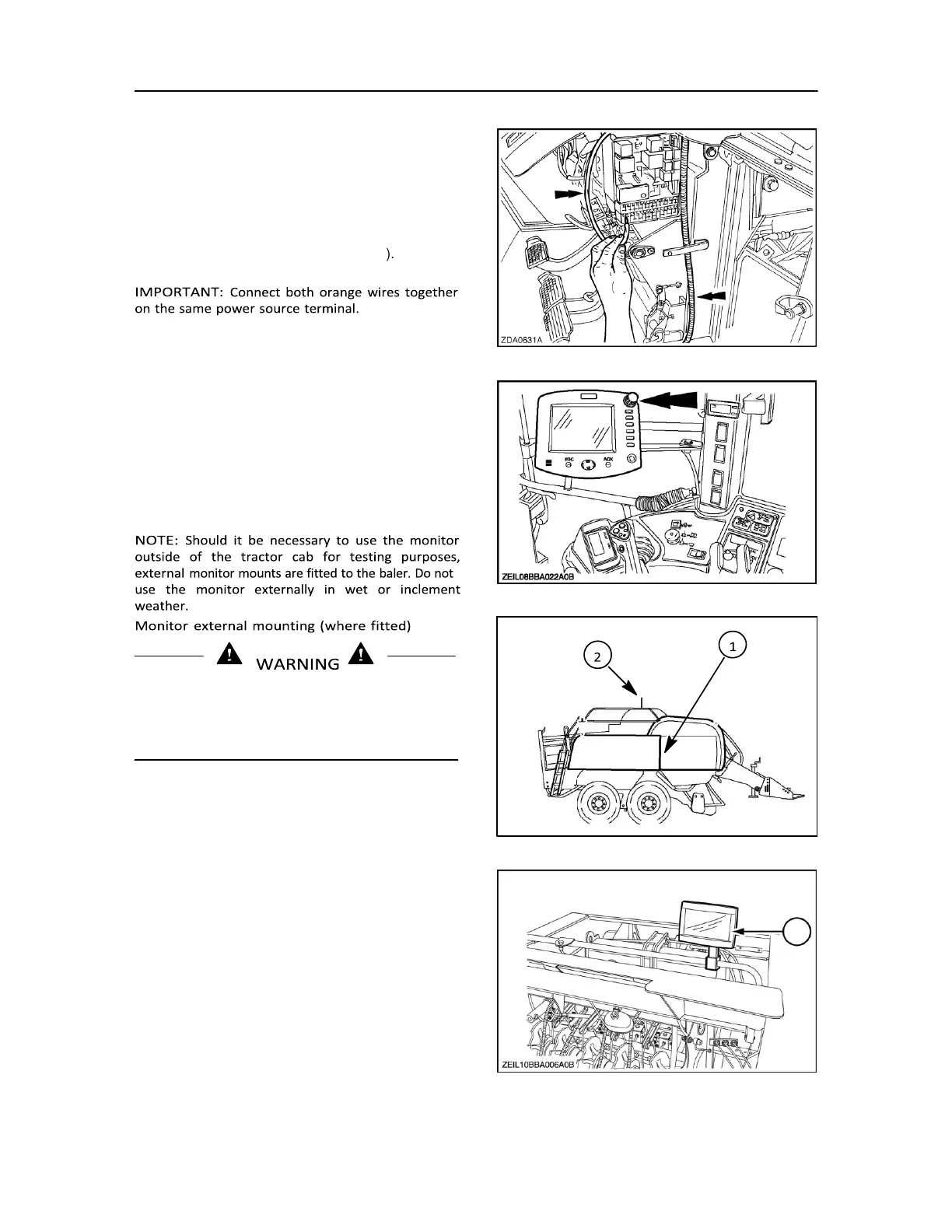
Position 1 : On the front of the RH twine box. Close
to the control box where you can check if for instance
a relay is working or not.
From position 1: the monitor can be lifted onto the
Position 2: On top of the knotter handrail pointing
back. For adjustment of the pre-load of the
load cell and the knotter mistie sensors.
not in use, box up the monitor and
toolbox for storage during winter, and/or if the baler
is parked or moved from place to place.