INTRODUCTION
BasicinstructionsFuseandrelaylocations
Themachineisequippedwiththreefuseboxlocations.Inthefrontconsole,asideconsoleboxandanexternal
location.
Frontconsole-EngineControlUnit(ECU)
fuseandrelay
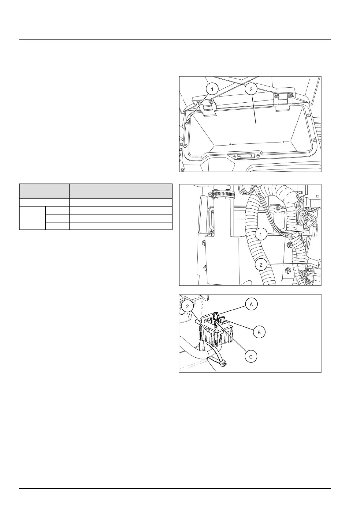
1.Openthemanualstoragecompartmentlocatedin
frontofthesteeringwheel.
2.Removethefourscrews(1).
3.Removethecompartmentinsert(2)toaccessthe
fuseandrelay.
RAPH12UTL0128AA1
Fuseorrelay
reference
Designation
(1)ECUB+70Asealedrelay
(A)ECUB+20Afuse
(B)ECUB+7.5Afuse (2)
(C)LAMBDASENSORB+7.5Afuse
RAPH12UTL0126BA2
RAIL12UTL0220AA3
4744159427/09/2012
10