Do you have a question about the Casio PX-300 and is the answer not in the manual?
Details on keyboard type, polyphony, and available tones.
Information on reverb, chorus effects, and metronome settings.
Specifications for auto-accompaniment rhythms and tempo control.
Details on preset tunes and the lesson function capabilities.
Capacity and operations for song recording and memory backup.
Information on pedal types, touch, transpose, and tuning.
MIDI implementation, headphone, line out, and line in specifications.
Power needs, speaker output, dimensions, and weight of the unit.
Table detailing the keyboard key matrix connections to controller ICs.
Explanation of the naming convention used for keyboard keys in diagrams.
Diagram showing the component layout of the main circuit board.
Instructions for removing the base plate and side covers.
Procedure for detaching the front panel and inner side cover.
Steps for removing the power and jack printed circuit boards.
Connecting peripherals and initiating the diagnostic test mode.
Details on RAM, ROM, and LED automatic testing procedures.
Procedures for testing buttons and pedal functionality.
Schematic diagram for the main circuit board assembly.
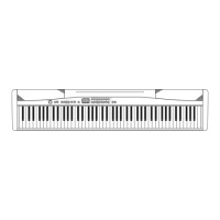
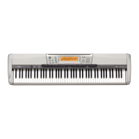
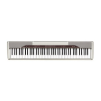
This document provides a comprehensive service manual for the Casio PX-300 High-Grade Keyboard, offering detailed information for maintenance, repair, and diagnostic procedures. It is designed for technicians and service personnel, covering various aspects from the overall system architecture to specific component layouts and troubleshooting steps.
The manual begins with a block diagram, illustrating the interconnections between the main functional units of the keyboard. This includes the MPU (Microprocessor Unit), keyboard matrix, button/LED controller, ROM, RAM, D/A converter, filters, power amplifier, and various input/output sections such as MIDI, pedal, headphones, and line in/out. This high-level overview helps in understanding the signal flow and the relationships between different modules, which is crucial for diagnosing system-level issues.
Following the block diagram, a detailed circuit description is provided, focusing on the key matrix and button matrix. The key matrix section maps out how each of the 88 piano keys (A0 to C8) is connected to the KC (Key Column) and FI/SI (Key Row) lines, indicating the specific key associated with each intersection. This information is vital for troubleshooting key response issues, identifying faulty key contacts, or replacing individual key components. Similarly, the button matrix details the connections for various control buttons on the console, such as "G.PIANO 1," "PERC ORGAN," "CHOIR," "MUSIC LIBRARY," "PLAY/STOP," "METRONOME," "SONG MEMORY," and "REVERB/CHORUS." This mapping is essential for diagnosing unresponsive buttons or issues with the control panel.
The manual then delves into the physical layout of the printed circuit boards (PCBs), presenting diagrams for the Main PCB (M412-MAA1), Console PCB (M412-CNA1), Volume PCB (M412-CNA2), Sub PCB (M412-PS1), Jack PCB (M412-PSA2), Power Switch PCB (M412-PSA3), Pedal PCB (M412-PSB4), and the Key PCBs (MCPK-KYA1, KYB2, KYA3). These diagrams show the placement of integrated circuits (ICs), resistors, capacitors, connectors, and other components, aiding technicians in locating specific parts during repair. The inclusion of "NO." markings on some PCBs suggests potential revision numbers or unique identifiers for manufacturing.
A significant portion of the manual is dedicated to disassembly and assembly procedures, which are critical for accessing internal components for repair or replacement. The instructions are presented in a step-by-step format, often accompanied by illustrations to guide the technician. The process begins with removing the base plate and various screws, followed by the side covers and front panel. Subsequent steps detail the removal of specific PCBs, such as the Power PCB, Jack PCB, Main PCB, Volume PCB, Console PCB, and LED PCB, along with the speakers and keyboard assembly. The instructions emphasize the importance of removing connectors and screws in a specific order. For instance, removing the keyboard involves a sequence of actions to detach it from the main chassis. The key PCBs themselves are also subject to disassembly, with instructions for removing rubber keys and individual key PCBs (MCPK-KYA1, KYB2, KYA3), noting the varying number of screws for each. This detailed guide ensures that the device can be taken apart and reassembled correctly without causing further damage.
For maintenance and troubleshooting, the manual includes a diagnostic program. This program allows technicians to perform various checks to identify faulty components or functions. The initial setup for the diagnostic program involves connecting an AC adaptor and a Sustain pedal, and setting the "Main" volume to MAX. It also notes that pedal or MIDI checks can be skipped if these components are not available. To start the program, specific button combinations are required, leading to a test mode where all LEDs light up. The diagnostic program includes an automatic test with RAM CHECK (indicated by "TONE1" LED for errors), ROM CHECK (indicated by "TONE2" LED for errors), and LED CHECK (where groups of LEDs light up repeatedly). A "CONTROL" button press confirms these checks, with a chord sound. Further checks include a BUTTON check, where buttons are pressed in a specific order, and an "NG tone" indicates an error or wrong sequence. A PEDAL check verifies the functionality of the "DAMPER" and "SOFT" pedals, with corresponding LED indicators and chord sounds. A HEADPHONE check involves connecting headphones to the LEFT jack and a tuning meter to the RIGHT jack, with LED indicators for "CHORUS" and "REVERB" and a requirement to check the tuning meter at 440 ± 2 cents. Finally, a MIDI IN/OUT check involves connecting MIDI IN and OUT terminals with a MIDI cable, with confirmation via the "CONTROL" and "A4 KEY" buttons. The diagnostic program concludes with specific LEDs lighting up and "00" appearing on the display, indicating its completion.
The manual also provides schematic diagrams for the Main PCB (M412-MAA1), Sub PCB (M412-PS1), Console PCB (M412-CNA1), Jack PCB (M412-PSA2), Volume PCB (M412-CNA2), Pedal PCB (M412-PSB4), and the Key PCBs (MPCK-KYA1, KYB2, KYA3). These diagrams offer a detailed view of the electronic circuits, including component values, connections, and signal paths. This level of detail is indispensable for advanced troubleshooting, component-level repair, and understanding the electrical behavior of the device.
An exploded view diagram is included, showing the various parts of the keyboard in an exploded perspective, with each component numbered. This visual aid helps in identifying the physical location and relationship of parts during disassembly and reassembly. The accompanying parts list provides a comprehensive inventory of all components, including their item number, parts code, parts name, specification, quantity, and remarks. The notes in the parts list clarify that cosmetic parts are excluded and advise contacting the spare parts department for refurbishment needs. It also states that prices and specifications are subject to change and refers to a separate "GUIDEBOOK for Spare parts Supply" for ordering. The parts list is categorized by PCB, such as Main PCB, Sub PCB, Jack PCB, Console PCB, Key board assy, and Case unit, further aiding in component identification and ordering.
The document concludes with a revision history, detailing updates to the manual over time. This includes replacements of the exploded view and parts list in various versions, as well as a note about an illustration replacement for the Main PCB. This revision history is useful for ensuring that technicians are using the most current and accurate information for service and repair.
| Polyphony (Maximum) | 32 notes |
|---|---|
| Speakers | 12cm x 2 |
| Amplifier Output | 8W + 8W |
| Power Supply | DC 12V |
| Digital Effects | Reverb (4 types), Chorus (4 types) |
| Metronome | Yes |
| Recorder | 2 tracks, 1 song |
| Terminals | MIDI IN/OUT |
| Included Accessories | Music stand, AC adaptor |
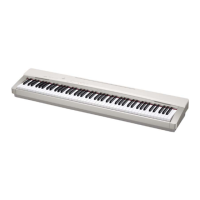
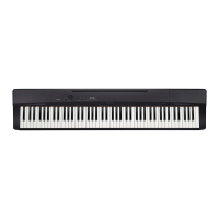
| Keyboard | 88 keys, weighted hammer action |