— 8 —
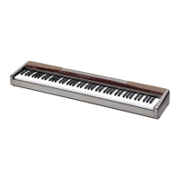
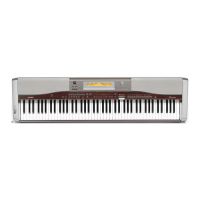
DISASSEMBLY AND ASSEMBLY(*EQUIVALENT MODEL PX-500)
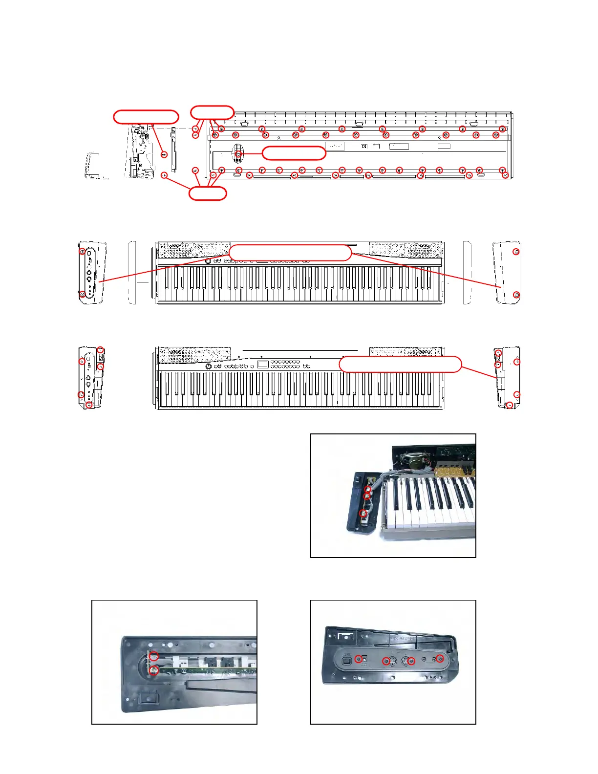
1. Remove 34 screws A at the bottom and then the base plate.
2. Remove ten screws B.
3. Turn the unit over so that the keyboard faces upward.
4. Remove four screws on the left and right sides and then remove the side covers on the outer sides.
5. Remove ten screws on the left and right sides and then the front panel.
6. Remove the side cover on the inner right side.
8. Remove two screws and then the Power PCB (M412-PSA3).
9. Remove four screws and then the JACK PCB (M412-PSA2).
■ Removing the Power PCB (M412-PSA3) and the JACK PCB (M412-PSA2)
7. Remove three connectors.
Screws B (×10)
Screw A
Screw A
Screws B (×10)
Side covers on the outer side
Side covers on the outer side