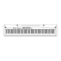
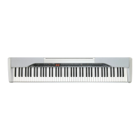
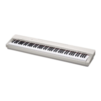
Do you have a question about the Casio PX-130 and is the answer not in the manual?
Layout of the Keyboard PCB MACP-KYA1.
Layout of the Keyboard PCB MACP-KYA2.
Layout of the Keyboard PCB MACP-KYB1.
Layout of the Keyboard PCB MACP-KYB2.
Layout of the Keyboard PCB MACP-KYC1.
Layout of the Keyboard PCB MACP-KYC2.
Layout of the Keyboard PCB MACP-KYD1.
Steps for removing the main panel of the instrument.
Procedure for removing the right side case.
Procedure for removing the left side case.
Steps to detach the main PCB (M900-MDA1) from the unit.
Instructions for detaching the sub PCB (M900-PSA1).
Steps to remove the console and volume PCBs.
Procedure for removing the power switch and jack PCB.
Instructions for removing the instrument's speakers.
Steps to remove the keyboard assembly (KY-ASSY).
Method for safely removing individual piano keys.
Procedure for correctly installing piano keys.
Steps for disengaging piano hammers from the mechanism.
Procedure for correctly mounting piano hammers.
Steps to remove keyboard PCBs KYC1, KYC2, and KYD1.
Steps to install keyboard PCBs KYC1, KYC2, and KYD1.
Steps to remove keyboard PCBs KYA1, KYA2, KYB1, and KYB2.
Steps to install keyboard PCBs KYA1, KYA2, KYB1, and KYB2.
Prerequisites and setup steps before starting diagnostic tests.
Instructions on initiating the diagnostic software.
List of tests performed by the diagnostic program and their notes.
Details of the automatic diagnostic test sequence.
Procedure for verifying the keyboard model.
Steps to check internal and external ROM versions.
Procedure for testing the functionality of all buttons.
Steps for verifying the operation of connected pedals.
Procedure for testing headphone output functionality.
Steps to verify USB connectivity and functionality.
Method for testing the responsiveness of all keys.
Procedure for checking the keyboard's flash memory.
| Polyphony | 128 notes |
|---|---|
| Tones | 16 built-in tones |
| Speakers | 2 x 8W |
| Amplifier Output | 8W + 8W |
| MIDI | Yes |
| USB | Yes |
| Touch Response | 3 sensitivity levels, Off |
| Lesson Function | Yes |
| Recorder | 2 tracks, 1 song |
| Metronome | Yes |
| Pedals | Included SP-3 |
| Power Consumption | 18W |
| Keyboard | 88-key, Scaled Hammer Action |
| Weight | 11.2 kg |
| Digital Effects | Reverb (4 types) |
| Built-in Songs | 60 songs |
| Terminals | USB, Pedal |
| Power Requirements | AC adaptor AD-A12150LW |
| Touch Sensitivity | 3 levels, off |
| Transpose | 25 steps (-12 to +12 semitones) |
| Connectors | USB, Pedal |
| Power Supply | AC adaptor AD-A12150LW |
| Included Accessories | Music stand |
| Recorder Capacity | Approximately 5, 000 notes |
| Tuning | A4 = 415.5Hz to 465.9Hz |