– 15 –
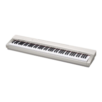
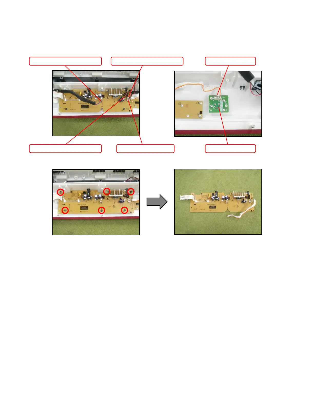
Removing the sub PCB (M900-PSA1)
Remove four connectors.1.
Unsolder the FFC connected to the M900-CNB2 PCB shown on the top right.2.
Remove six screws and then the sub PCB (M900-PSA1).3.
Connector (Left speaker) Connector (Power switch)
Connector (Right speaker)
Connector (M900-HPA1) M900-CNA2 PCB
FFC (M900-PSA1)