— 20 —
M. Removing the LCD/Touch Panel
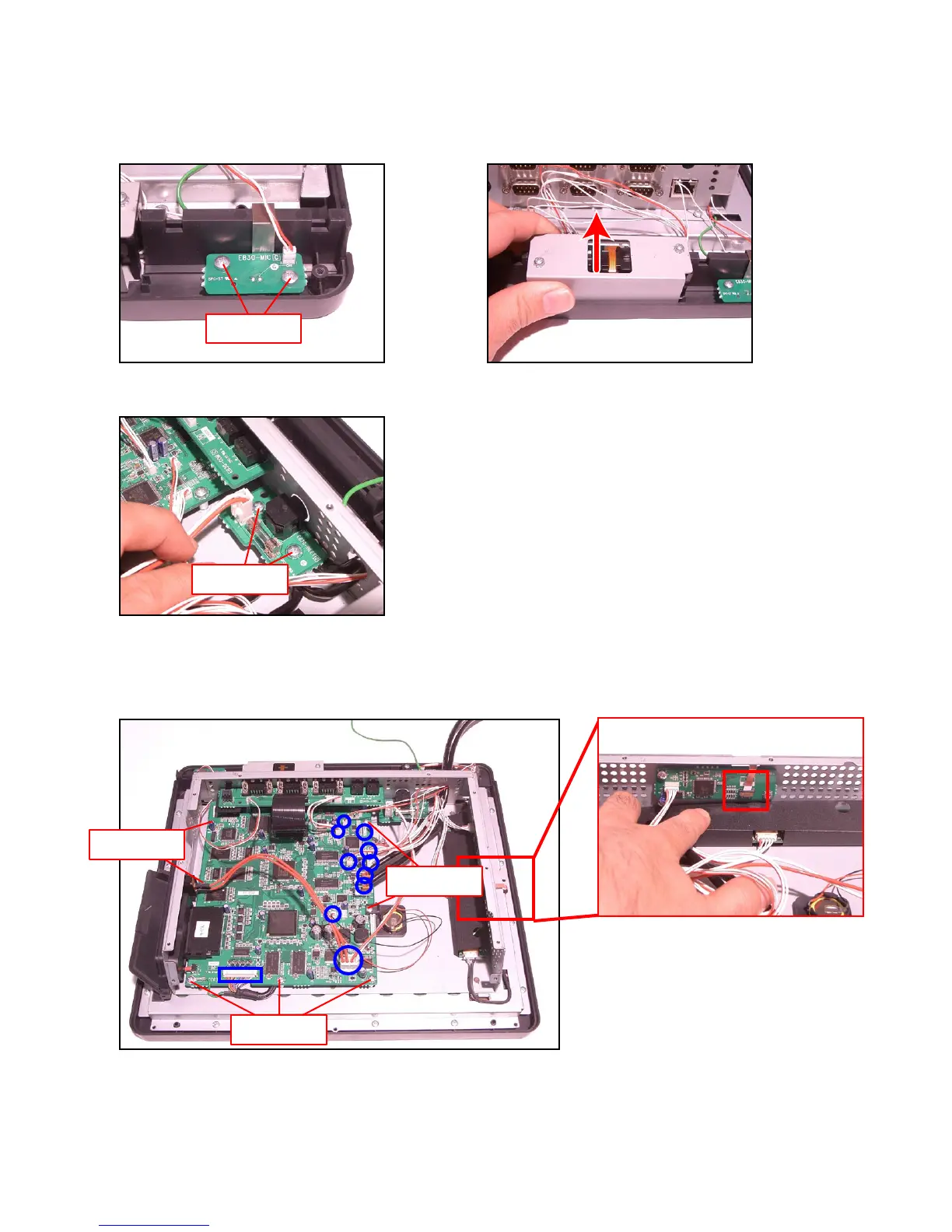
M-1. Remove two screws and remove Mic PCB (E830-MIC).
M-2. Disengage and remove the MCR unit from the Main Unit.
Screws (S7)
M-4. Unplug 10 connectors and disconnect 1 FPC.
M-5. Remove seven screws.
M-6. Release the Touch Panel PCB (E830-TP) connector lock and disconnect the FPC.
Screws (S9)
Screws (S9)
Screws (S9)
M-3. Remove two screws and remove the Power Supply PCB (E830-INLET).
Screws (S5)
 Loading...