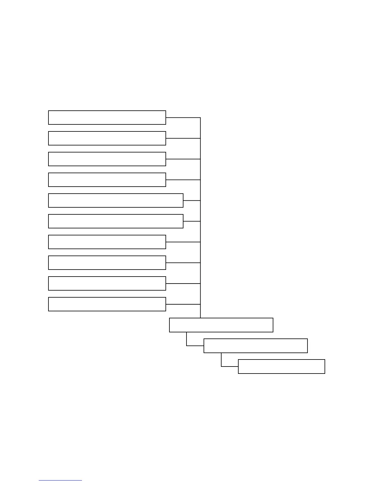
EasyManuals Logo
Home>Casio>Touch terminals>QT-6600

Casio QT-6600 Service Manual

Casio QT-6600
136 pages
To Next Page IconTo Next Page
To Previous Page IconTo Previous Page
Page #27 background imageLoading...
Page #27 background image
— 24
4. ASSEMBLY
Assembling
See the flowchart below for the order of re-assembling major units.
M. Assembling the Stand
L. Assembling the B-case Assy Block
K. Assembling the Rear Display Block
I. Assembling the Mic PCB (E830-MIC)
H. Assembling the LED PCB (E830-E6)
G. Assembling the Inverter Unit
F. Assembling the Touch Panel PCB (E830-TP)
E. Assembling the Power Supply PCB (E830-INLET)
D. Assembling the COM PCB (E830-COM)
C. Assembling the Main PCB (E830-1)
B. Assembling the MCR
A. Assembling the LCD/Touch Panel
J. Assembling the Rear Display

Other manuals for Casio QT-6600

Questions and Answers:

Question and Answer IconNeed help?

Do you have a question about the Casio QT-6600 and is the answer not in the manual?

Casio QT-6600 Specifications

General IconGeneral
BrandCasio
ModelQT-6600
CategoryTouch terminals
LanguageEnglish

Related product manuals