— 8 —
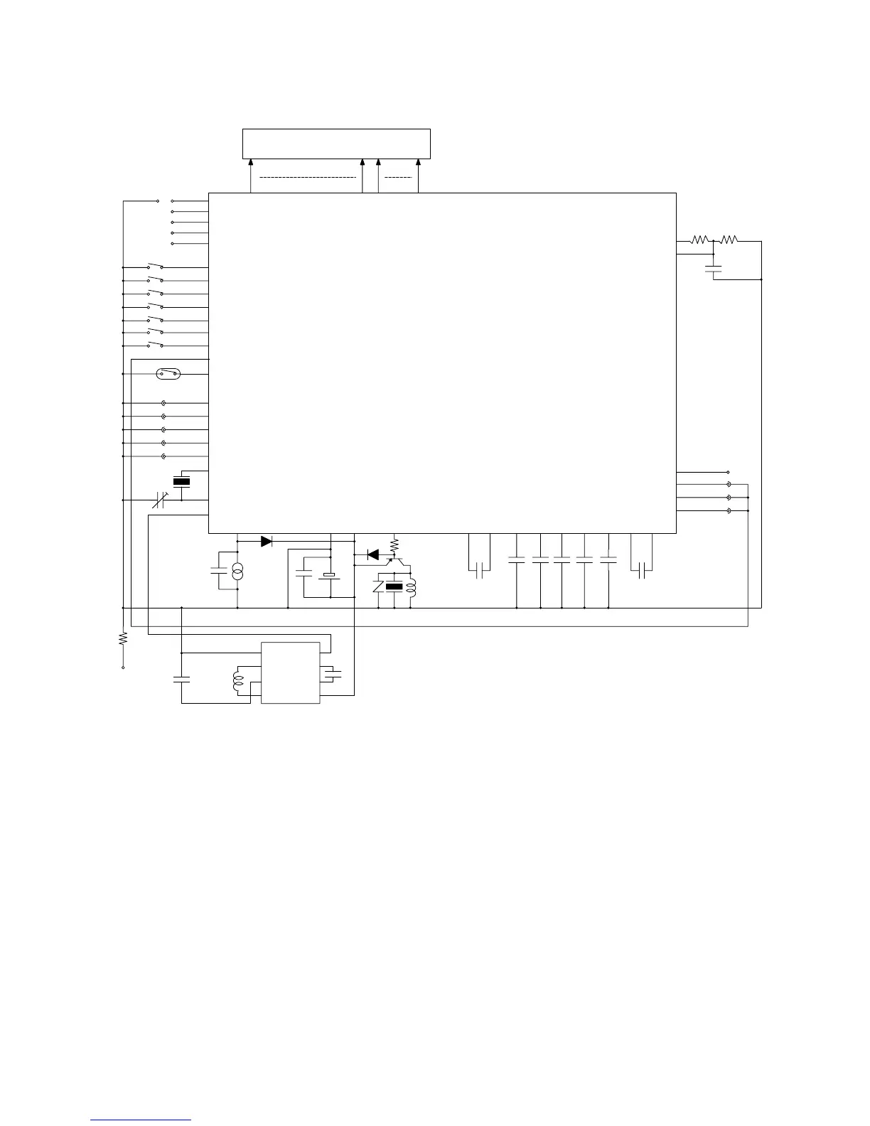
3-2. CIRCUIT DIAGRAM
LSI
TOTAL 106PINS
BONDING 101PINS
✽2
✽2
✽4
✽4
✽4
✽3
✽3
✽3
✽2
✽3
✽5
✽6
✽7
✽7
✽3
✽3
✽8
LCD (2.8V 1/3b 1/5d)
GND VDD2 VCH VDD3 VC1 VC2VDD1BD VDSPVC3 VC4 VHFVSC
C3
C2C5 C1C4C6
C7
BAT
C8
LL1
Tr1
PZ
Di1
SC
C9
Z
Di2
R1
CLF1
E'
Cel
EL
INV
LL2
L+
VOUT
L–
GND
CLF2
V+
BACK
FRONT
GNDB
Rb
Xtal
CT
SK
S2
S1
S5
S3
SA
S4
SB
XTB
LD1
XT
T1
T2
T3
KI1
KI2
KI3
KI4
KI5
KI6
KI7
KI8
KI9
AC
T4
R1
R2
R3
N1
N2
L1 - - - - L55 LC1 - - - LC5 SDO SCK CSBSDI
SCR
SCIN
RP1RP2
Cp
KC4
KC3
KC2
KC1
VPM✽1
✽9
✽10
✽1✽1 ✽1✽1
✽ 1. No bonding
✽ 2. Soldering pads (for switching modules) are not used in
this module, and are all open.
✽ 3. Latch type key
✽ 4. Short (Soldering) (R trimming)
✽ 5. Inclination sensor
✽ 6. GNDB is used for the bias on the back of the tip.
✽ 7. Short (Soldering) (N trimming)
✽ 8. L28~L30 are used as the static drive pins.
✽ 9. KC2 is used in this module.
✽ 10. KC3 is used in this module.