8
JOINING THE FRAME
USE
LOADING AND CHANGING THE WEDGE CARTRIDGE ON MACHINE
Pull the wire with ball of the wedge pusher spring F (fig.2, p1) fully out.
If there is a cartridge on machine, holding the wire pulled out, remove it by simply sliding out
the cartridge.
Holding the wire pulled out, put a new cartridge on machine and pay attention that it is fully
inserted in the wedge distributor’s window.
Release gently the wire with ball of the wedge pusher spring F.
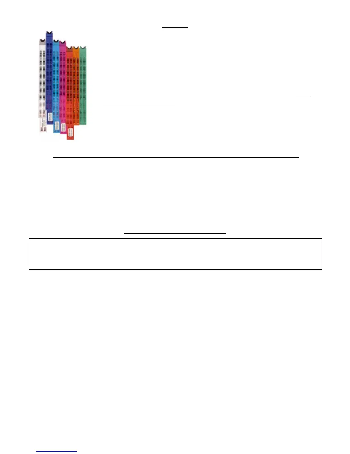
The joining is performed by using metal wedges, a Cassese inven-
tion, designed to ensure very tight corners. Seven sizes are available :
3, 4, 5, 7, 10, 12 and 15 mm. They come in throw-away cartridges
that are colour-coded per size for easy identification. Cartridge
wedges exist in two versions : NORMAL for soft and normal timbers
and HW for very hard timbers. These hardwood wedges are
to be
used only on hardwoods. Your CS 79 machine is designed to use all sizes
of Cassese cartridges without having to change any parts on the machine
or having to adjust anything.
For the long term performance and reliability of your CS 79, only use
genuine CASSESE cartridge wedges. Beware of counterfeit products.
MEANS OF ASSEMBLY
After selecting and setting the stapling positions (page 5 & 6), adjusting the assembly angle
(page 7), checking the distance between the top presser and the moulding (page 7) and loading
the best suited type (normal or hardwood) and size of wedges (page 8),
1- Put the first (left-hand) moulding in front of the fence B1 and push it so that its mitre end
reaches the other fence B2.
2- Holding it so, put the second moulding chop against fence B2 and slide it until it reaches the
first moulding.
3- Holding the mouldings in place against each other, hold the backfences B1 & B2 with your
thumbs and make the angle assembly slide backwards until the lever P1 reaches the limit stop B.
You can eventually tighten the intermediate lever P3 to be sure that the position remains fixed.
4- Still holding the mouldings well profiled against each other, push the foot pedal P (Fig 2, p.1)
until the green light V (Fig 1 p1) comes on that indicates that the wedge has been fully inserted. If
you intend to stack a second (or third) wedge in the same position, just push the footpedal again
until V-light comes on. In this case using (tightening) the lever P3 will enable you to stack them
more easily.
5- If there is a second stapling position chosen (with lever P2), just repeat the same operation by
pushing forward the mouldings and the angle assembly of the machine until P2 reaches the limit
stop B. And repeat step 4 above.