WEDGE
EXIT
WEDGE
EXIT
FRONT OF MACHINE
P2
B
P1
P3
B1
B2
B
E
E
E
6
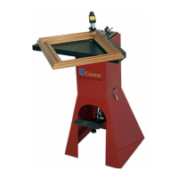
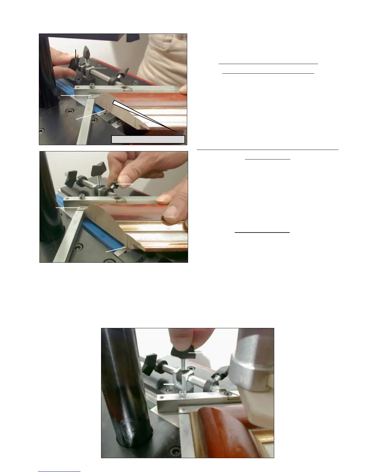
Standing in the work position used of reference for explanations (behind the machine; see
Fig 2, page 1), with your left hand, put the first moulding chop in front of the left (1
st
)
backfence B1 and bring the chop in contact
with the right (2
nd
) backfence B2.
For the stapling position close to the inside
of the frame :
Move the 90° joining angle backwards, until
you have reached the furthest
position to the inside of the frame where you
want to insert wedge(s).
Then bring the lever P1 against the limit stop
B and tighten the lever.
Now the two positions of joining are set and
the machine’s 90° angle can move only
within the limits of these two positions.
In case you would like to insert wedges in between these two positions, or if you are
working with a very small moulding and would like to insert wedges only in one place, you
can use the lever P3 located on the limit stop B.
This intermediate lever P3 also enables you to stack wedges (on top of each other in the
same position) without risk of missing the stacking operation (not pushing the first wedge
deeper inside).
For the stapling position close
to the outside of the frame :
Move forward the 90° joining angle assembly
E until the place where you want to insert the
wedge(s) has been reached by the WEDGE
EXIT (see picture). Then bring the lever P2
against the limit stop B and tighten it.