CASTLE, INC TSM-21 Bosch Motor Carriage Install Page 5 of 25
1.2 Identification of Operating Features and Controls
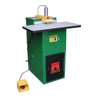
Router Stop Plate: Located just inside the rear door, this black metal
plate extends through the top of the case and along the right side of
the Clamp Guard. The position of this plate determines the size of the
“Web.”
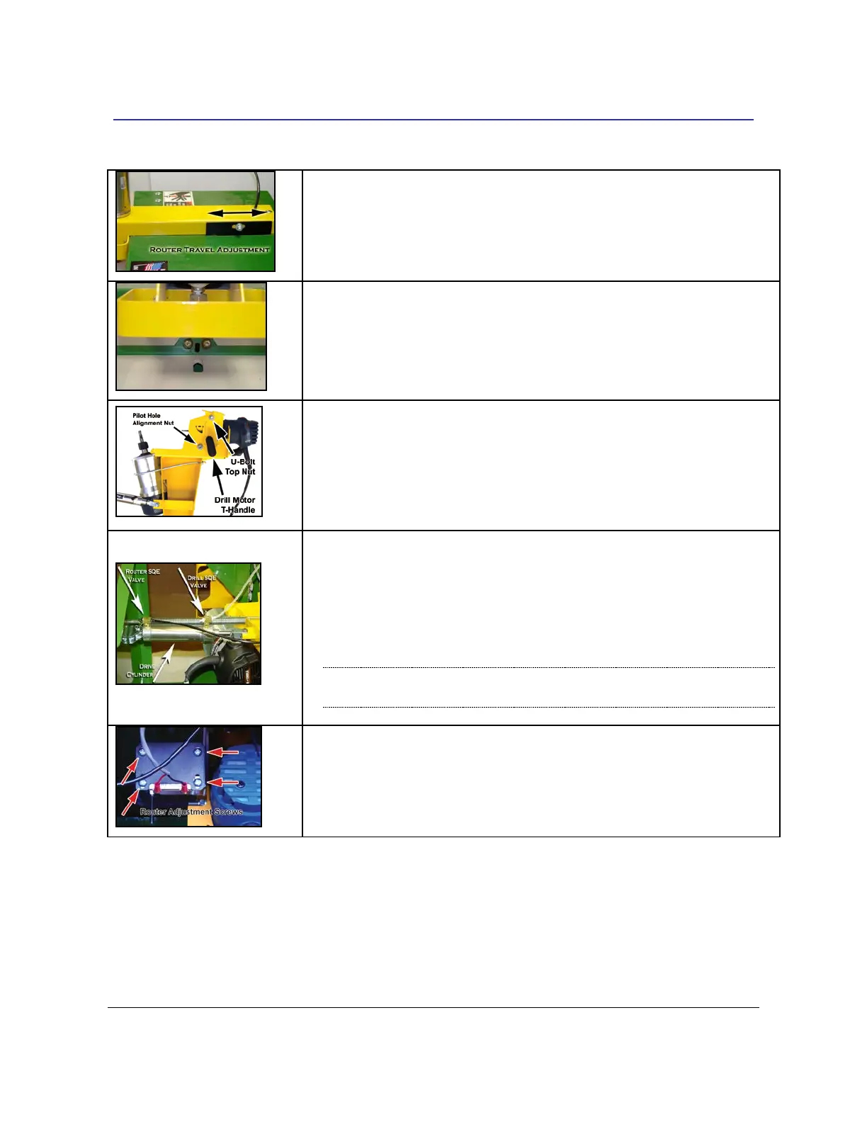
Safety Buttons: Two small, silver button-head screws under the
Clamp Guard detect if a work piece is in place for pocketing. The
machine will not cycle unless these buttons are depressed
simultaneously with the Foot Pedal.
Motor Carriage: The Motor Carriage is the yellow, pivoting A-frame
structure inside the machine. Both the Router Motor and the Drill
Motor are mounted to this carriage. The forward and back carriage
motion during the machine cycle is provided by the Drive Cylinder.
Drive Cylinder: This double-acting pneumatic cylinder connected to
the Motor Carriage and the machine case, moves the carriage
through the routing and drilling phases of the cycle. When the
cylinder rod extends (moving the carriage toward the rear) the router
cuts the pocket. When the cylinder rod retracts (moving the carriage
forward) the pilot drill bores the pilot hole into the pocket.
NOTE: SQE valves are replaced by elbow fittings in models with
Serial Number 62481 and higher.
Router Stop Switch: This magnetic proximity switch is mounted on
the Router Stop Plate inside of the machine. At the full extension of
the routing stroke, the carriage interrupts this switch to signal the start
of the drilling stroke.