4
ASSEMBLY
Assemble the unit according to the following procedure. Learn how to adjust each part as well.
* In addition to the tools provided, please prepare a screw driver.
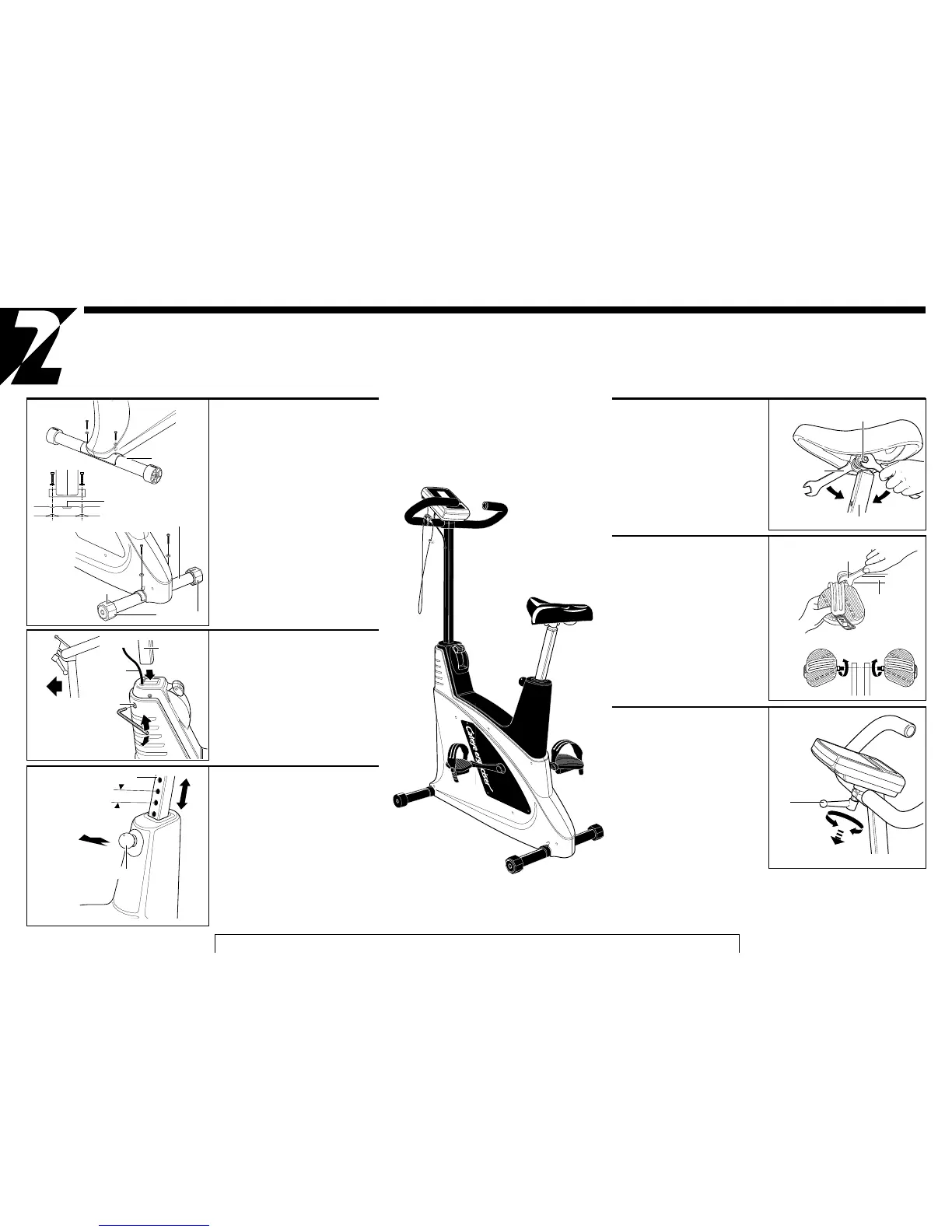
1. Attaching the leg pipes
• Remove the two screws from each leg pipe.
• Place the front leg pipe under the front end of
the main body as Fig. 1 and fasten it with the
screws securely.
• Place the rear leg pipe under the rear end of
the main body as Fig. 2 and fasten it equally.
CAUTION: Place the leg pipes with the "TOP"
mark facing upward.
ADJUSTMENT: Turn the level adjusters if
necessary, in order to compensate the floor
unevenness.
*When the marking line is at the top, the rear
leg is at the same level as front.
8
6
4
2
1
3
5
7
2. Mounting the handlebar post
• Confirm the front side of the handlebar post
(Fig. 3) and insert it into the main body watch-
ing not to bite the 7P cable. (Fig. 4)
• Use the hexagon wrench to fasten the handle-
bar post fastening screw until the handlebar
post cannot wobble.
CAUTION: Do not tighten the handlebar fas-
tening screw excessively.
3.
Seat post position(ADJUSTMENT)
• Pulling the spring lock pin allows the seat post
to slide up and down. (Fig. 5)
• Adjust the seat post to an appropriate height
and release the spring lock pin, and move the
seat post slightly up or down.
• The spring inside the spring lock pin drives the
pin into the nearest hole on the seat post, and
locks it in position.
• The pitch of the seat post holes is 1 inch
(approx. 25 mm).
CAUTION: Do not pull the spring lock pin
while mounted. The seat post may drop down
suddenly.
Fig. 2
Marking line
Fig. 5
Seat post
Pull
Spring lock pin
7P cable
Loosen
Handlebar post
Fig. 4
Fig. 3
Pipe with casters
Fig. 1
TOP mark
1
2
3
Level adjusters
Rear
Front
Tighten
Rear leg pipe
Handlebar post
fastening screw
Front
Pitch 1" (approx. 25 mm)
5
4. Mounting the saddle
• Lift up the seat post to a proper height for
saddle mounting.
• Mount the saddle at the top of the seat
post as Fig. 6.
• Adjust the saddle angle to make it hori-
zontal, and use the #13 end of the spanner
wrenches to tighten the nuts from both
sides.
5. Attaching the pedals
• Attach the pedals to the crank as Fig. 7
and fasten them firmly using the #15 end
of the wrench provided.
• Be sure to identify R and L of the pedal
with the engraved mark.
• Fasten clockwise the R pedal, and coun-
terclockwise the L pedal. (Fig. 8)
6.
Adjusting the handlebar angle
(ADJUSTMENT)
• The handlebar height is adjusted by rotat-
ing the handlebar.
• The handlebar can be rotated when the
handlebar adjusting lever is loosened.
Hold the handlebar at an appropriate
angle and tighten the handlebar adjusting
lever. (Fig. 9)
• The handlebar lever is loosened when
turned clockwise from the riding position.
When it is pulled down, it turns idle. (The
Fig. 9 shows the situation where the con-
trol unit is already mounted.)
Fig. 7
#15 Wrench
Crank
Fig. 8
Left(L) Front Right(R)
Handlebar adjusting
lever
Fig. 9
Fig. 6
#13 Wrench
Seat post
6
5
4
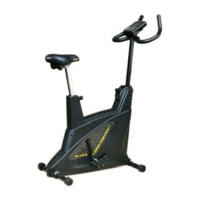
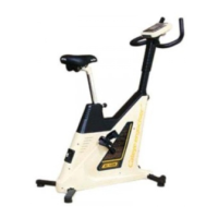
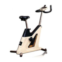
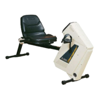
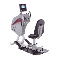
Assembly completed
(Control Unit already mounted)
Nut
Loosen
Tighten
Idle
EC-3200