Check Method of Causes
Explanation Figures
Repair Method
Cateye Ergociser EC-5000 Service Manual
13
No Display of Cadence when the Pedal is Rotated. (4)
T-2
No Display of Cadence when the Pedal is Rotated. (4)
T-2
CDC Sensor Set
CDC Sensor Cable
CDC Sensor Set
Turn Board
Cable Connector
Red Cable
(Terminal 1)
Black Cable
(Terminal 4)
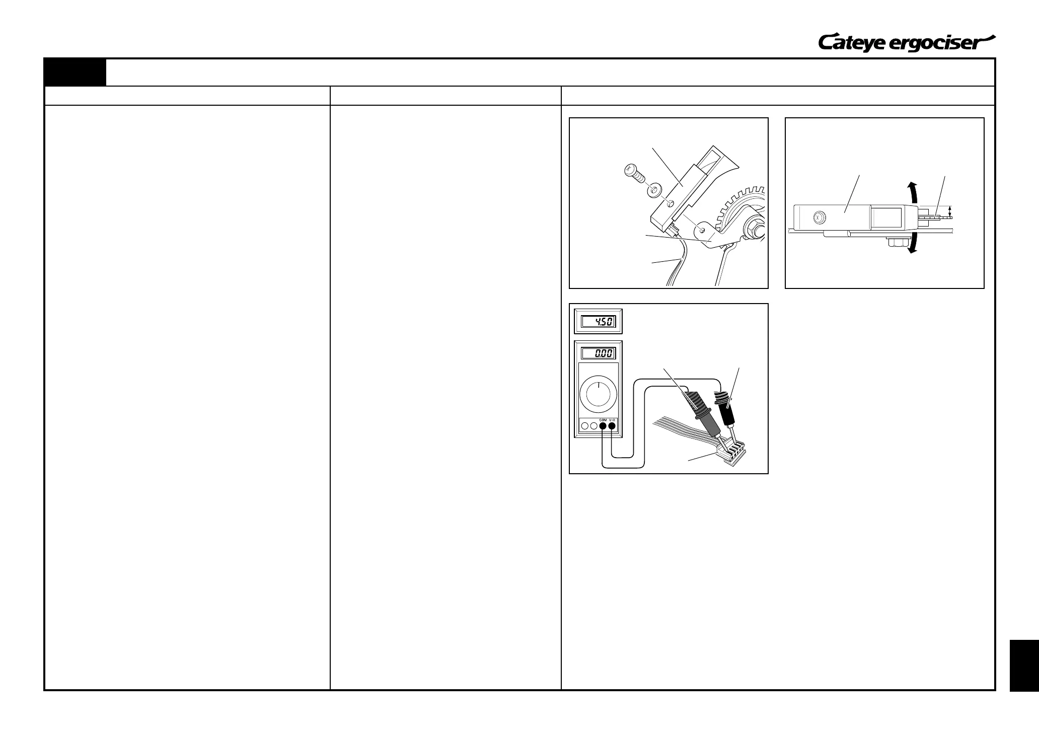
[3] Checking the CDC Sensor (Continued)
8. Replace the CDC sensor set with a new one.
A.Remove the CDC sensor set by loosening screws. (Fig. 14)
B.Detach the CDC sensor cable from the CDC sensor set.
C.First, connect the CDC sensor set and the CDC sensor
cable, and then mount it to the CDC sensor metal base.
(Fig. 14)
D.Rotate the CDC sensor around the screw, and adjust the
sensor so that it can be positioned to parallel with the CDC
magnet with the condition that the sensor does not touch the
magnet. (Fig. 15)
9. Connect the 5P cable to the power supply board, and check
the voltage. (Fig. 16)
A.Turn on the power of the main unit.
B.Slowly move the pedal while measuring the voltage across
the terminals 1 and 4 at the cable connector of the 5P cable
(5P connector at the side of the control unit connection).
(Fig. 17)
Terminal 1 is for plus (+) and Terminal 4 is for minus (-).
C.The CDC sensor is working fine when the voltage frequently
changes between approx. 5V and 0V.
[Judgment]
ⓦ When the voltage check is found to be all right, the possible
cause is the breakage of the CDC sensor. In this case, you
need to take actions as specified in the repair method (g)
as described at the right.
ⓦ When the voltage is incorrect, the possible cause is the
breakage of the power supply board. In this case, you
need to take actions as specified in the repair method (h)
as described at the right.
(g) Replace the CDC sensor set.
(See [ES-6: Replacing the CDC Sensor Set].)
(h) Replace the power supply board.
(See [ES-3: Replacing the Power Supply
Board].)
Fig.14
Fig.16
Fig.15
Parallel
Nomal condition: Frequently shifting
between 0V & 5V
CDC Sensor Metal
Base