Cateye Ergociser EC-5000 Service Manual
29
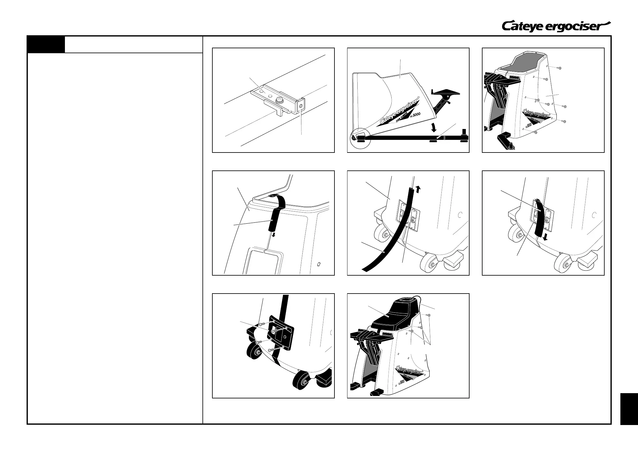
Mounting the Frame Covers
D-2
Mounting the Frame Covers
D-2
Frame Metal Base
Frame Cover
Mole
Fig.1
Frame Cover
Inlet Unit
Inlet Unit
Mole
Mole
Frame Cover
Center Cover Fixing Screw
5P Cable
Inlet Cover
Center Cover
Frame Cover
Speed Nut
1. Check if the direction of the speed nuts on the 14 frame metals
(seven pieces at either side) is set as depicted. (Fig. 1)
If some nuts are set in wrong directions, set them in the correct
direction.
2. Put the frame cover on the frame, by hooking it at the front leg.
(Fig. 2)
3. Using frame cover fixing screws (7 at either side), fix the right
and left frame covers. (Fig. 3)
4. Insert the mole in between the right and left frame covers. For
the pedal side, the mole should be inserted from the top. (Fig.
4)
For the front side, the mole should be divided into up and down
side and inserted at the inlet area. (Figs. 5 and 6)
5. Mount the inlet cover by using four screws. (Fig. 7)
6. Put the center cover. (Fig. 3)
During this procedure, the 5P cable should be put through the
hole at the front of the center cover, and pull the tip of the cable
out of the center cover.
7. Fix the center cover by using center cover fixing screws (3
pieces at either side). (Fig. 3)
8. Assemble the entire Ergociser.
(See [Starting up 1: Let's start with Assembling] of the Cateye
Ergociser Model EC-5000 Operating Instructions.)
Frame
Fig.2
Fig.3
Fig.4 Fig.5
Fig.6
Fig.7
Fig.8