Cateye Ergociser EC-5000 Service Manual
30
ES-1
ES-1
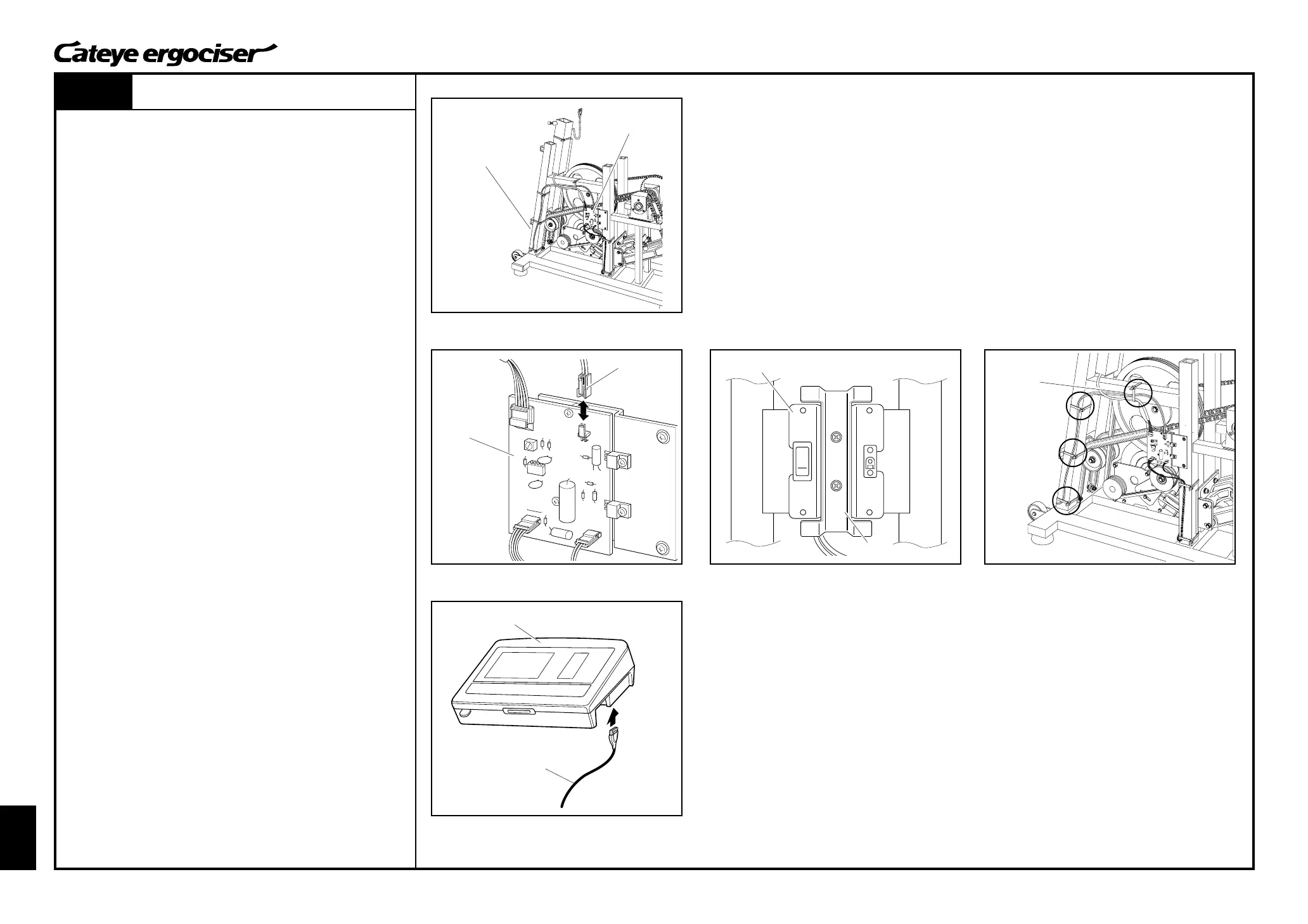
Replacing the Wiring within Frame (Inlet Metal Base Set)
(1)
Inlet Metal Base
Inlet Sopprt Metal
General Figure
Inlet Metal Base
Control Unit
5P Cable
REMOVAL
1. Remove the frame cover.
(See [D-1: Removing the Frame Covers].)
2. Remove the 2P connector at the power supply board. (Fig. 1)
3. Detach the inlet metal base and inlet support metal by loosen-
ing two screws. (Fig. 2)
4. Cut the cable holder with a nipper or the like. (Fig. 3)
ASSEMBLE
1. Mount a new inlet metal base on the frame by using the inlet
support metal base and two screws. (Fig. 2)
2. Connect the 2P connector to the power supply board. (Fig. 1)
3. Perform tests on the parts as specified for mounting and re-
placing the parts.
[Tests]
A.Connect the control unit and the 5P cable without mounting
the cover. (Fig. 4)
B.Turn on the power of the main unit, and check that the
display on the control unit appears.
C.Then, turn off the power and detach the 5P cable from the
control unit.
4. By using a cable holder, fix the power cable and the 5P cable
to the frame. (Figs. 3 and 4)
As depicted in Fig. 1, the power cable and the 5P cable should
be bundled together before fixing them.
5. Assemble the frame cover.
(See [D-2: Mounting the Frame Covers].)
Replacing the Wiring within Frame (Inlet Metal Base Set)
Power Supply Board
Power Supply
Board
2P Connector
Fig.1
Fig.2
Fig.3
Fig.4