Cateye Ergociser EC-5000 Service Manual
31
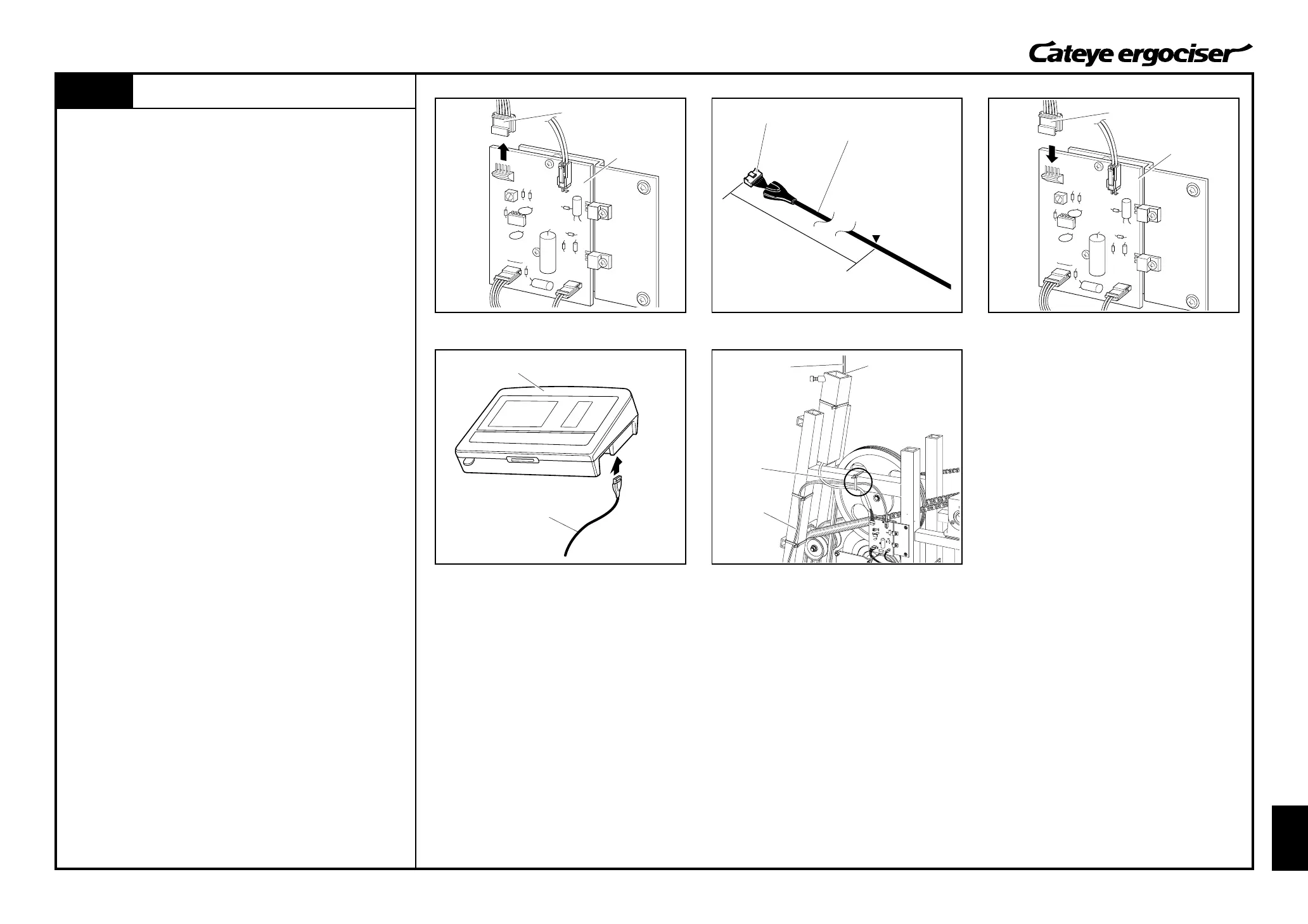
Replacing the 5P Cable
ES-2
Replacing the 5P Cable
ES-2
Fig.1
Cable Connector
5P Cable
93cm
Put a Mark
5P Connector 5P Connector
Mark
5P Cable
(1)
Control Unit
5P Cable
Power Supply Board
Power Supply Board
REMOVAL
1. Remove the frame cover.
(See [D-1 "Removing the Frame Covers."])
2. Detach the 5P connector at the power supply board. (Fig. 1)
3. Cut the cable holder which fixes the 5P cable to the frame, and
detach the 5P cable.
ASSEMBLE
1. Put a mark at a place approx. 93cm from the control unit side
cable connector of the 5P cable. (Fig. 2)
2. Connect the 5P connector at the end of the 5P cable to the
power supply board. (Fig. 3)
3. Perform tests on the parts as specified for mounting and re-
placing the parts.
[Tests]
A.Connect the control unit and the 5P cable without mounting
the cover. (Fig. 4)
B.Turn on the power of the main unit, and check that the
display on the control unit appears.
C.Then, turn off the power and detach the 5P cable from the
control unit.
4. Fix the 5P cable with a cable holder. (Fig. 5)
Also, fix the 5P cable to the frame so that the marked position
should align with the upper edge of the frame.
As depicted in Fig. 1, the 5P cable should be fixed together
with the power cable.
5. Assemble the frame cover.
(See [D-2: Mounting the Frame Covers].)
Power Cable
Fig.2
Fig.3
Fig.4
Fig.5