11
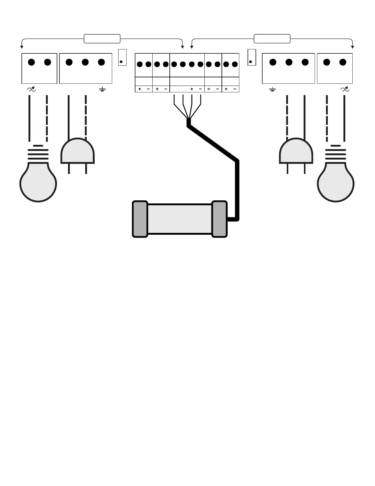
CEL-200 Wiring
Minimum Level Adjustment Procedure:
In manual mode, set the level of the zone to be adjusted to 1%.
Using a small screwdriver, adjust the corresponding potentiometer
until the desired lighting intensity is achieved for the 1% level.
MINIMUM
ADJUST
ZONE 1
L1
L2/N L2/N
120/240
V AC
0-10V
INPUT 1
0-10V
OUTPUT 1
0-10V
OUTPUT 2
0-10V
INPUT 2
MINIMUM
ADJUST
ZONE 2
120/240
V AC
ZONE 1 ZONE 2
L1
L2/N L2/N
LUX SENSOR
A B
*Sensor DLS02
* To extend the light sensor cable, use Belden 9842 / 3107A
or an equivalent cable for RS-485 applications (2 twisted pairs, 120 Ohms).
It is recommended to solder the splices and cover them with heat-shrink tubing
to make the connection waterproof.
( Optional, not included )
For bi-color lighting with the chromatic mode:
Connect the lighting with the lowest Kelvin to output 1.
Connect the lighting with the highest Kelvin to output 2.
Refer to the sensor installation manual
for connection details.