23
cdvigroup.com
EN
ATRIUM A22
2-Door Controller
INSTALLATION MANUAL
EN
ATRIUM A22
2-Door Controller
INSTALLATION MANUAL
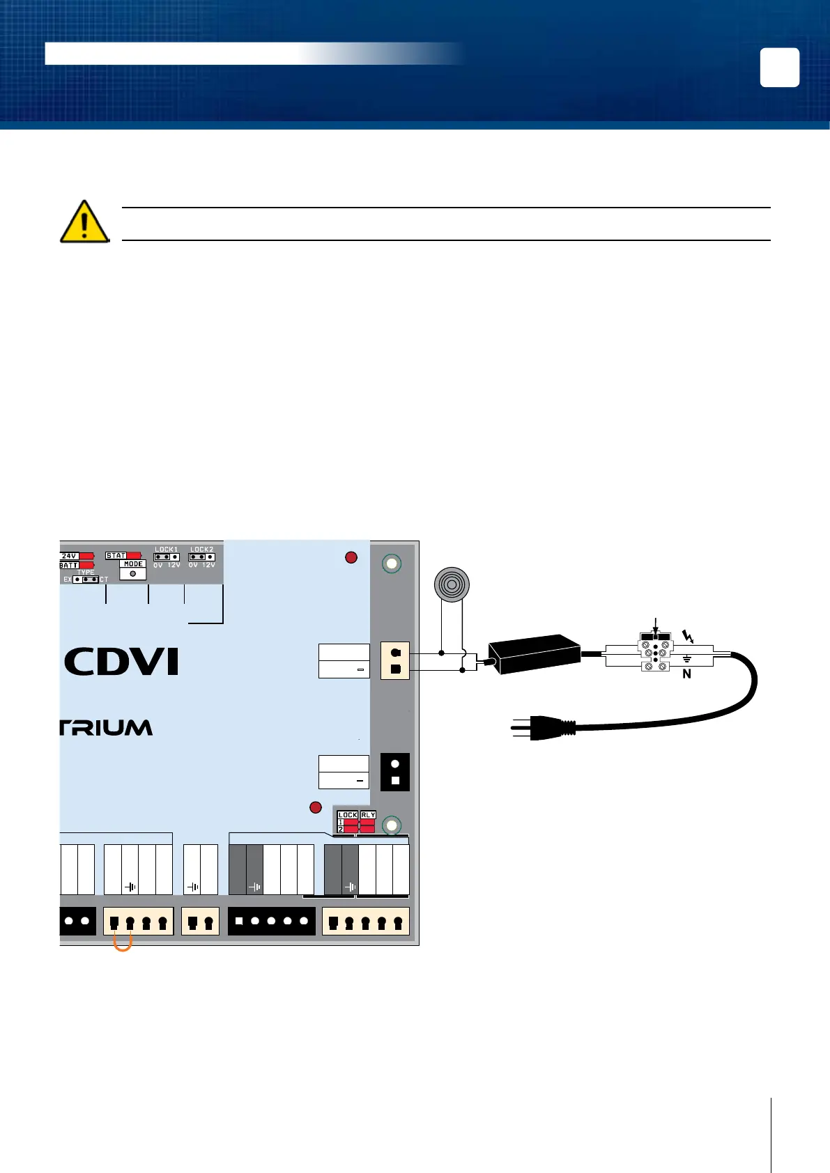
POWER SUPPLY
Do not power up the A22 until all connections are completed.
The module operates from any 120/240 Vac sources using the supplied AC/DC power supply and provides fully
monitored power solutions using:
• Smart Battery Deep discharge prevention with automatic electronic cut-o.
• Programmable & Adaptive battery charging algorithm (250mA (default), 320mA, 500mA, or 1A).
• Intelligent battery monitoring & charging algorithms allowing optimum performance using standard
lead acid or gel cell type batteries.
• Real Time Monitoring algorithm for ‘Battery Low/Disconnect/Reversal’ and ‘Insucient Main Power’.
AC Source
The AC to DC power supply is pre-installed in the A22 box but needs to be connected to the PCB. Simply plug
the two pin terminal to the input power supply.
INPUTS/
OUTPUTS
RS485
LOCAL
BUS
BATTERY
(12V DC)
INPUT
POWER
SUPPLY
STATUS
LOCK 1
SETTING
LOCK 2
SETTING
INPUTS
LOCKS
A22
2-Door Web-Based IP Module
DOOR 1
DOOR 1
DOOR 2
DOOR 2
DATA 1
Red LED 1
Green LED 1
Buzzer 1
DATA 0
+12V DC
DATA 1
Red LED 2
Green LED 2
Buzzer 2
DATA 0
+12V DC
Com. Relay 1
N.O. Relay 1
N.C. Relay 1
Lock output 1
Com. Relay 2
N.O. Relay 2
N.C. Relay 2
Lock output 2
REX 1
+12V DC
Door Contact 2
REX 2
+12V DC
Tamper Switch
+24V DC
-
+12V DC
-
+12V DC
A+
B
-
Input 1
Input 2
Output 1
+12 V DC
Output 2
ETHERNET
24V DC INPUT
BATTERY
Red
Power Supply
LED Indicator
Power Supply:
Input: 120-240Vac, 1.2A, 50Hz/60Hz
Output: 24Vdc @ 2.5A
(Do not connect to a receptacle controlled by a switch).
Fuse Rating:
250VAC, 2.5 A
(-55C to +125C)
White
Neutral
Live
Ground
See “Recommended Wiring” section for more information on wiring type, size, and maximum length.