26
cdvigroup.com
EN
ATRIUM A22
2-Door Controller
INSTALLATION MANUAL
EN
ATRIUM A22
2-Door Controller
INSTALLATION MANUAL
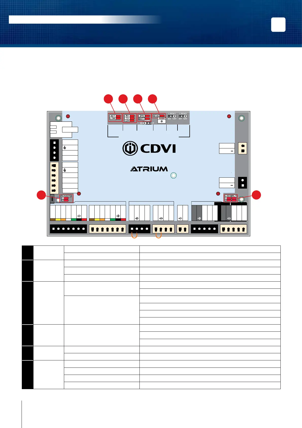
LED INDICATORS
The ATRIUM A22 has several status LEDs that are very useful to diagnose problems when using or installing the
ATRIUM system. Refer to the following picture to locate the LEDs on the ATRIUM A22. All LEDs are explained in
the following pages.
INPUTS/
OUTPUTS
RS485
LOCAL
BUS
BATTERY
(12V DC)
INPUT
POWER
SUPPLY
ETHERNET
LOCAL
BUS
STATUS
LOCK 1
SETTING
LOCK 2
SETTING
READERS INPUTS
LOCKS
A22
2-Door Web-Based IP Module
DOOR 1
DOOR 1
DOOR 2
DOOR 2
DOOR 1 DOOR 2
DATA 1
Red LED 1
Green LED 1
Buzzer 1
DATA 0
+12V DC
DATA 1
Red LED 2
Green LED 2
Buzzer 2
DATA 0
+12V DC
Com. Relay 1
N.O. Relay 1
N.C. Relay 1
Lock output 1
Com. Relay 2
N.O. Relay 2
N.C. Relay 2
Lock output 2
Door Contact 1
REX 1
+12V DC
Door Contact 2
REX 2
+12V DC
Tamper Switch
+24V DC
-
+12V DC
-
+12V DC
A+
B
-
Input 1
Input 2
Output 1
+12 V DC
Output 2
ETHERNET
24V DC INPUT
BATTERY
MODULE TYPE
SYSTEM STATUS
1
5
6
2 3 4
1
ETHERNET ACT Green LED ashing: Data transmitted/received.
LNK Green LED: Ethernet network detected.
2
LOCAL BUS RX Green LED ashing: Data received on local bus.
TX Green LED ashing: Data transmitted on local bus.
12V Green LED: 12V on local bus.
3
24Vdc Input
/ Battery
24V DC IN Green LED: A22 is powered properly.
Red LED: No primary power.
BATT BATT Green LED: Primary power present and battery charging.
O LED: Primary power present and battery full.
Red LED: No battery or battery not properly connected.
Red LED ashing: Battery power is below 11.8Vdc.
4
STATUS STAT Flash once per second: Firmware is operating normally.
Flash rapidly: Firmware is upgrading.
Blink once per 3 seconds: Card enrollment mode.
5
READERS #1 Green LED ashing: Data received from Reader #1.
#2 Green LED ashing: Data received from Reader #2.
6
LOCK &
RELAY
LOCK 1 Green LED: Door 1 Lock Relay is active/triggered.
LOCK 2 Green LED: Door 2 Lock Relay is active/triggered.
RLY1 Green LED: Auxiliary Relay 1 is active/triggered.
RLY2 Green LED: Auxiliary Relay 2 is active/triggered.