11
РУССКИЙ
RU
Введение
Описание
Технические характеристики
Эксплуатационные ограничения (IEC 60974-1)
Методы подъема аппарата
Распаковка
Монтаж
Подключение к сети питания
Правила применения
Сварка электродом
Сварка TIG
Техобслуживание
Выявление причин неисправностей и их
устранение
Процедура демонтажа и монтажа сварочного
аппарата
Электротопографическая схема
Цветовая маркировка
Обозначения электрической схемы
Значение графических символов на сварочном
аппарате
Значение графических символов на пластине
Список запчастей
Заказ запасных частей
Введение
Благодарим Вас за приобретение нашего изделия. Для обе-
спечения наилучшей отдачи от оборудования и максимально-
го срока службы его частей необходимо прочитать и строго со-
блюдать инструкции по эксплуатации, приведенные в данном
руководстве, и нормы безопасности, приведенные в при-
лагаемой брошюре. Если для оборудования потребуется те-
хобслуживание или ремонт, эти инструкции помогут вам найти
наиболее подходящее решение всех ваших проблем, однако
заказчикам по вопросам техобслуживания и ремонта обору-
дования рекомендуется обращаться в мастерские нашей тех-
службы, так как они имеют соответствующую оснастку и ква-
лифицированный постоянно обучаемый персонал. Все маши-
ны и аппараты нашего производства подвержены постоянно-
му усовершенствованию, поэтому оставляем за собой право
вносить изменения в конструкцию и оснащение оборудования.
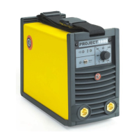
Описание
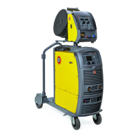
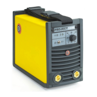
PROJECT - это инвертор, который может использоваться для
профессиональной сварки рутиловыми и щелочными элек-
тродами. Инвертор чрезвычайно прост в эксплуатации, обе-
спечивает оптимальные результаты сварки и благодаря сво-
ей компактности и малому весу может использоваться в лю-
бой ситуации (в мастерских, при ремонте, на стройплощад-
ке и т. д.) Основные характеристики этого сварочного аппа-
рата следующие:
• Компактность и малый вес для облегчения переноса.
• Серийный ремень для облегчения переноса.
• Класс защиты IP 23 S, позволяющий использовать аппарат
в самых неблагоприятных рабочих условиях.
•
Селектор процесса: сварка электродом и сварка TIG (ду-
говая сварка вольфрамовым электродом в среде инертно-
го газа).
• Автоматические функции «Hot Start» и «Hot Start».
•
Функция Antisticking для предупреждения прилипания элек-
тродов.
•
Сварка TIG (сварка вольфрамовым электродом в среде
инертного газа) с зажиганием типа «Lift».
•
Кроме того, генератор отвечает всем нормам и директивам,
действующим в Европейском Сообществе.
Технические характеристики
Общие технические характеристики аппарата кратко приво-
дятся в таблице 1.
Таблица 1
Модель
PROJECT
1300 1600
Однофазное электропитание
50/60 Гц
В 230
Сеть питания: Z
max
(*) Ω 0,19
Потребляемая мощность
@ I
2
Max
кВ 6,3 6,7
Плавкий предохранитель
замедленного действия
(I
2
@ 100%)
A 16
Коэффициент мощности / cosφ
0,62/0,99 0,60/0,99
Максимальная кпд η 0,82
Вторичное напряжение
холостого хода
В 60
Вторичное напряжение
холостого хода
A 5÷130 5÷160
Ток, используемый
@ 100% (40°C)
A 80 90
Ток, используемый
@ 60% (40°C)
A 100 105
Ток, используемый
@ 25% (40°C)
A 130 160
Используемые электроды мм 1,6÷3,25 1,6÷4
Директивы
IEC 60974-1
IEC 60974-10
Класс защиты IP 23 S
Класс изоляции F
Размеры
мм 315 - 230 - 135
Вес кг 6,1 6,3
(*) Сеть питания Z
max
: максимально допустимое значение
полного сопротивления сети в соответствии со стандартом
EN/IEC 61000-3-11.
ВНИМАНИЕ: Это оборудование не соответствует стан-
дарту EN/IEC 61000-3-12. При подключении к системе об-
щего пользования низкого напряжения ответственность
за проверку, с обращением, при необходимости, к операто-
ру распределительной сети, возможности подключения обо-
рудования, возлагается на монтажника или эксплуатацион-
ника оборудования.
10
2000HA39
FIG. D
FIG. C
2000HA29
TIG welding (Fig. C)
TIG welding melts the metal of the workpiece, using an arc
struck by a tungsten electrode.
The fusion bath and the electrode are protected by gas (Argon).
This type of welding is used to weld thin sheet metal or when
elevated quality is required.
1) Connecting the welding cables:
•
Connect one end of the gas hose to the gas connecter
on the TIG torch and the other end to the Argon cylin-
der and open it.
• With the machine switched off:
-
Connect the earth cable to the snap-on connector
marked + (positive).
-
Connect the relative earth clamp to the workpiece or
to the workpiece support in an area free of rust, paint,
grease, etc..
-
Connect the TIG torch power cable to the snap-on con-
nector marked - (negative).
2) Adjust the welding current using the potentiometer (Pos. 3,
Fig. A).
3) Adjust the process switch (Pos. 6, Fig. A) to TIG (switch le-
ver moved to the left-hand side).
4) Start the welding machine by selecting pos. 1 on the line
switch (Pos. 7, Fig. A).
5) The white LED (Pos. 1, Fig. A) indicates that the welding
machine is powered and ready to work.
6) Adjust the gas flow by manually turning the valve on the
TIG torch.
7) The “Lift” function strikes the arc when the TIG torch elec-
trode comes into contact with the workpiece and is then
removed (see Fig. D).
8) Carry out TIG welding.
PART TO BE WELDED
The part to be welded must always be connected to earth in or-
der to reduce electromagnetic emission. Much attention must
be afforded so that the earth connection of the part to be weld-
ed does not increase the risk of accident to the user or the risk
of damage to other electric equipment.
When it is necessary to connect the part to be welded to earth,
you should make a direct connection between the part and the
earth shaft. In those countries in which such a connection is
not allowed, connect the part to be welded to earth using sui-
table capacitors, in compliance with the national regulations.
Maintenance
ATTENTION: before carrying out any inspection of the inside
of the generator, disconnect the system from the supply.
SPARE PARTS
Original spare parts have been specially designed for our equi-
pment. The use of non-original spare parts may cause varia-
tions in performance or reduce the foreseen level of safety.
We decline all responsibility for the use of non-original spare
parts.
GENERATOR
As these systems are completely static, proceed as follow:
•
Periodic removal of accumulated dirt and dust from the inside
of the generator, using compressed air. Do not aim the air
jet directly onto the electrical components, in order to avoid
damaging them.
• Make periodical inspections in order to individuate worn ca-
bles or loose connections that are the cause of overhea ting.
Possible problems and remedies
The supply line is attributed with the cause of the most com-
mon difficulties. In the case of breakdown, proceed as follows:
1) Check the value of the supply voltage.
2) Check that the power cable is perfectly connected to the
plug and the supply switch.
3) Check that the power fuses are not burned out or loose.
4) Check whether the following are defective:
• The switch that supplies the machine.
• The plug socket in the wall.
• The generator switch.
NOTE: given the required technical skills necessary for the re-
pair of the generator, in case of breakdown we advise you to
contact skilled personnel or our technical service department.
Procedure for welder assembly
and disassembly
Proceed as follows:
•
Undo the 4 screws securing the cover to the front and rear
panel.
• Remove the cover from its seat.
Proceed the other way round to re-assemble the welder.
11
11
11
12
12
12
12
12
12
13
14
14
14
14
16
16
17
18
19
20-21
22
 Loading...