5
piping to remove the distorting load, and realign the pump
and driver.
9) The pump and driver alignment must again be checked at the
operating temperature and alignment corrected under the hot
condition.
10) After about two weeks of normal pump operation the pump
and driver alignment should again be checked under the hot
condition. If alignment is still correct, the driver feet may be
doweled to the baseplate. If the alignment has changed,
realign the unit and recheck after two weeks. NOTE: Refer to
MC 1.2.34 FBP when Dean FRP baseplates are used.
SUCTION AND DISCHARGE PIPING
Suction and discharge nozzle sizes of Dean pumps are selected
for proper performance of the pumping unit and are not intended
to determine the suction and discharge pipe sizes. Pipe sizes must
be determined by the user based on the system requirements.
Suction piping should have a minimum friction loss and thus
should be as short and straight as possible with a pipe diameter
as large as economically feasible for the flow rate handled.
Suction piping should never be smaller in diameter than the suc-
tion nozzle size. When the suction piping is larger than the suction
nozzle size an eccentric reducer is required at the suction flange
and must be installed with the taper located on the underside to
eliminate air or vapor pockets. The section of piping attached to
the suction flange of the pump should be straight for a length of
eight pipe diameters or more.
Discharge piping may be the same size as, larger, or smaller than
the discharge nozzle as the system flow may demand.
In new installations or rebuilt systems, dirt, pipe scale, welding
slag, and general construction debris may get into the piping. It is
important to prevent this material from entering the pump and
damaging pump parts, mechanical seal faces, or seal chamber
packing. Mechanical seal parts are especially subject to damage
even by very small particles. To prevent damage, a strainer or fil-
ter installed in the suction line is recommended. Commercially
able to the pump and should be considered at the time the system
is designed.
NOTE: See page 26 for Installation of pHP self-priming pumps.
PUMP AND DRIVER ALIGNMENT
Proper running life of a pump and driver unit depends on the accu-
racy with which the axis of the driver shaft coincides with the axis
of the pump shaft when the unit is running. Although pumps and
drivers are check aligned at the factory, this is only to confirm that
the unit can be aligned in the field and handling during shipment
and installation will cause the alignment to change.The pump and
driver alignment must always be checked and corrected before the
baseplate is grouted to the foundation and again before the pump
is first started. If the baseplate mounting instructions have been
carefully fol lowed, no difficulties in making the alignment should
be experi enced. Failure to properly align the unit will result in
vibra tion, short bearing life, and reduced mechanical seal or shaft
packing life.
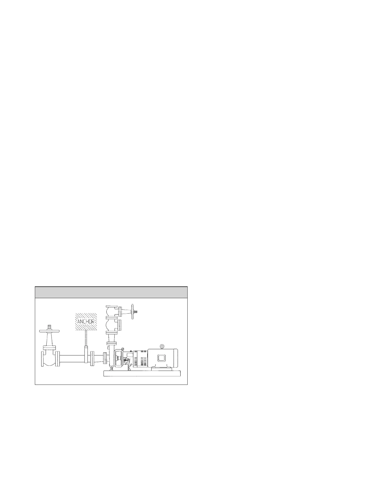
Pumps are not constructed to be used as pipe anchors. Both suc-
tion and discharge piping must be supported independently of the
pumping unit and thermal expansion joints provided to guard
against expansion loads on the pump. Pipes should be anchored
between the expansion joint and the pump and as closely to the
pump as possible. Failure to provide proper piping support and
expansion joints may impose strains on the pump ing unit which
will result in serious misalignment. Any and all loads upon the
pump must be with-in the maximum allowable values given in the
section titled “Allowable Nozzle Loads” on page 6.
No allowance for thermal expansion is made for motor driven
units in mounting the driver. Allowance for turbine mounting
should be in accordance with the turbine manufacturer’s recom-
mendations. Final alignment must always be checked and correct-
ed at the operating temperatures of the pump and driver.
Misalignment of the two shafts is of two kinds. The first of these is
angular misalignment where the axis of one shaft is at an angle
from the other. The other is offset alignment where the center of
one shaft is offset from the center of the other shaft. These effects
usually occur together so that both angular and offset misalignment
are present.
Coincident alignment of the driver and pump shaft is measured at
the faces of the coupling hubs. Because of the variety of coupling
types furnished at customer’s request, the procedure here given is
general in nature but may be applied by simple adaption to most
coupling types.
The first step is to remove the spacer from the coupling. To one of
the remaining coupling hubs, firmly seated on the shaft, attach a
dial indicator. Let the indicator button ride on the face of the other
coupling hub and near the outside diameter. Rotate the shaft on
which the dial indicator is mounted, allowing the indicator button
to move on the stationary coupling hub. The indicator dial move-
ment will show the difference in distance between the two hubs.
This indicates the amount of angular misalignment between the
hubs and therefore the shaft axes. Good practice suggests align-
ment to within 0.002" T.l.R.
available strainers or filters as recommended by their manufactur-
ers can do an excellent job. In addition, special filtering and
mechanical seal flushing may be required. Consult your Dean rep-
resentative. Suction line screens or strainers may usually be
removed when, after several days of use, no dirt has been collect-
ed and the system is clean.
Remember that screens and filters in the suction line are restrictive
devices which reduce the net positive suction head (NPSH) avail-
TYPICAL PUMP PIPING