6
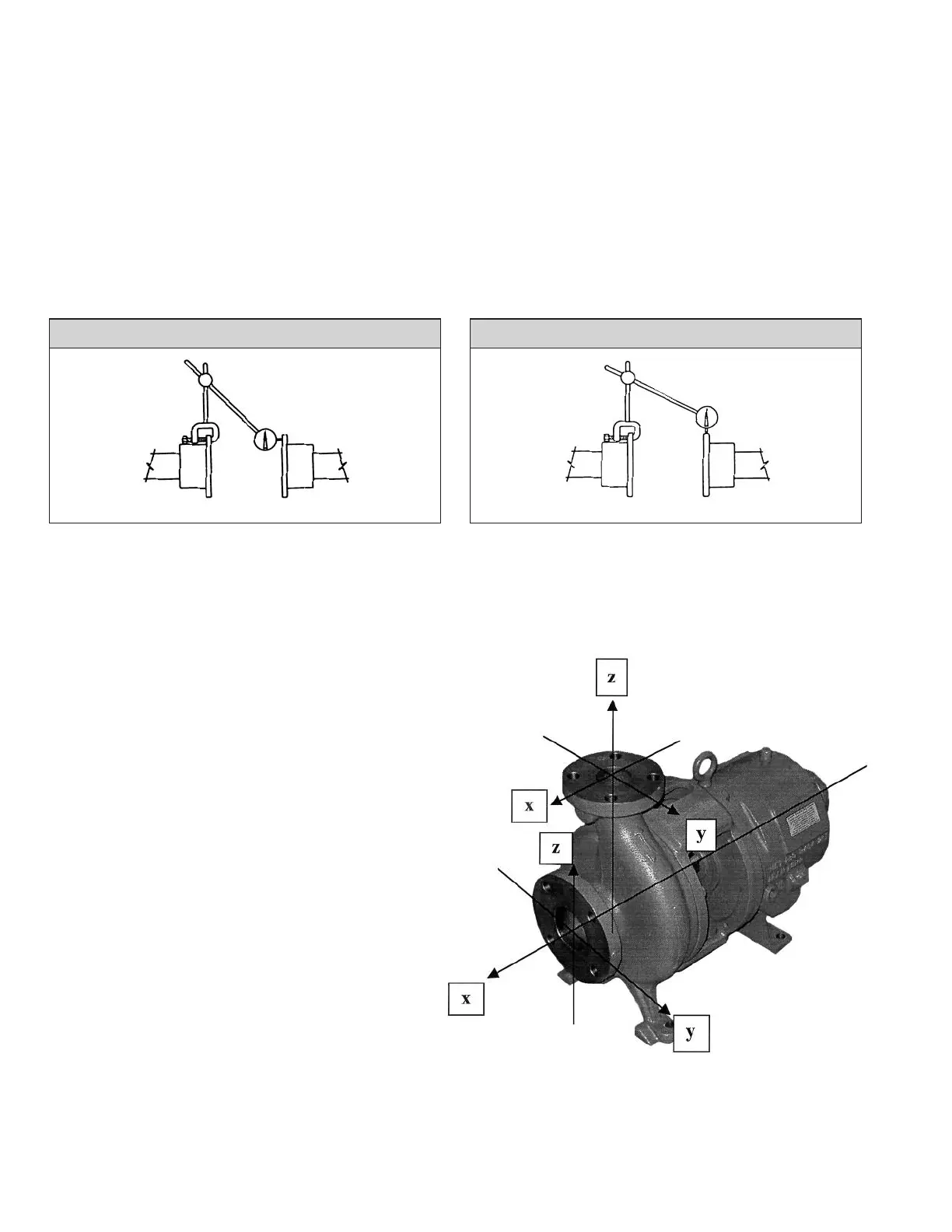
To check the offset alignment, mount the dial indicator as above
except with the indicator button on an outside diameter of the sta-
tionary coupling hub. Rotate the shaft on which the dial indicator
is mounted, allowing the indicator button to ride on the outside
diameter of the stationary hub. The indicator dial move ment will
show the difference in the center locations of the two shafts. Good
practice suggests alignment to within 0.002" T.I.R.
Angular and offset alignment is adjusted by placing thin metal
shims under the driver mounting feet to bring the drive into
exact alignment with the bolted down pump. If misalignment is
of major proportions, the baseplate has been improperly installed
on the foundation and must be releveled before proceeding with
alignment.
After each change, it is necessary to recheck both angular and
offset alignment of the coupling. After driver is aligned to the
pump, tighten all hold-down bolts and then recheck alignment.
Allowable error of shaft alignment is somewhat dependent on
the coupling type. However, the closer the running alignment,
the better the running life will be.
INDICATOR SETUP TO READ OFFSET MISALIGNMENT
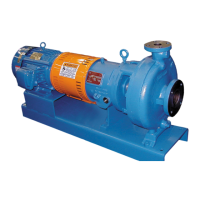
INDICATOR SETUP TO READ ANGULAR MISALIGNMENT
ALLOWABLE NOZZLE LOADS
The allowable loads given below and the procedure for application are as specified by the “American National Standard for Centrifugal
and Vertical Pumps for Allowable Nozzle Loads”, ANSI/HI 9.6.2-2001. For additional information and application, including examples,
refer to this standard.
SYMBOLS
F
xs
= applied force on x-axis on suction nozzle
F
ys
= applied force on y-axis on suction nozzle
F
zs
= applied force on z-axis on suction nozzle
M
xs
= applied moment about x-axis on suction nozzle
M
ys
= applied moment about y-axis on suction nozzle
M
zs
= applied moment about z-axis on suction nozzle
F
xd
= applied force on x-axis on discharge nozzle
F
yd
= applied force on y-axis on discharge nozzle
F
zd
= applied force on z-axis on discharge nozzle
M
xd
= applied moment about x-axis on discharge nozzle
M
yd
= applied moment about y-axis on discharge nozzle
M
zd
= applied moment about z-axis on discharge nozzle
F
xs
max = allowable force on x-axis on suction nozzle
F
ys
max = allowable force on y-axis on suction nozzle
F
zs
max = allowable force on z-axis on suction nozzle
M
xs
max = allowable moment about x-axis on suction nozzle
M
ys
max = allowable moment about y-axis on suction nozzle
M
zs
max = allowable moment about z-axis on suction nozzle
F
xd
max = allowable force on x-axis on discharge nozzle
F
yd
max = allowable force on y-axis on discharge nozzle
F
zd
max = allowable force on z-axis on discharge nozzle
M
xd
max = allowable moment about x-axis on discharge nozzle
M
yd
max = allowable moment about y-axis on discharge nozzle
M
zd
max = allowable moment about z-axis on discharge nozzle