49
1. PARTS AND COMPONENTS
The graphics in this manual are schematic representations and may not exactly match the
product.
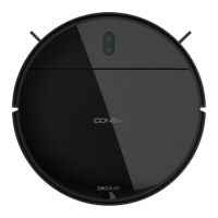
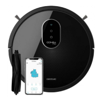
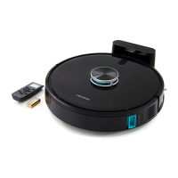
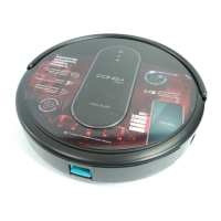
Robot vacuum cleaner Fig. 1.1:
1. Back Home
2. Start/Pause button
3. Top cover
4. Anti-collision sensor
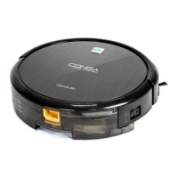
5. Water-tank release button
6. Dust tank
7. Free-detection sensor
8. Side brushes
9. Drive wheels
10. Charging terminals
11. Omnidirectional wheel
12. Battery
13. Suction mouth
Robot vacuum cleaner light indicators
- Steady blue light: the robot is cleaning, or charge is complete
- Flashing blue light: Standby
- Steady white light: the robot is looking for the charging base
- Flashing white light: charging
- Flashing blue/white light: error
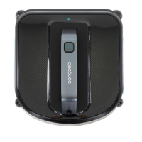
Charging base. Fig. 1.2:
1. Operation light indicator
2. Charging connector
3. Charging terminals
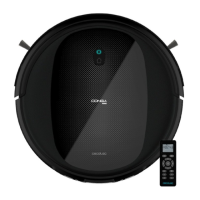
Remote control. Fig. 1.3:
1. On/O button
2. Auto mode
3. Edge mode
4. Manual mode
5. Random mode
6. Suction power level