Page 19For technical questions, please call 1-800-444-3353.Item 60328
NOTICE
Clean the Airbrush IMMEDIATELY after use.
Delayed or inadequate cleaning will permanently clog the Airbrush.
SAFETYOPERATIONMAINTENANCE SETUP
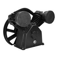
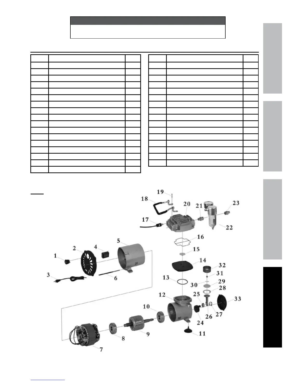
Compressor Parts List and Assembly Diagram
Part Description Qty
1A Power Switch 1
2A Front Cover 1
3A Power Cord 1
4A Capacitor 1
5A Rear Housing 1
6A Screw 4
7A Stator 1
8A Bearing 1
9A Rotor 1
10A Bearing 1
11A Foot 4
12A Front Housing 1
13A O-Ring 1
14A Cylinder Block 1
15A O-Ring 1
16A O-Ring 1
17A Pressure Switch 1
Part Description Qty
18A Handle 1
19A Screw 4
20A Cylinder Head 1
21A Connector 1
22A Water Trap/Air Pressure Gauge 1
23A Connector 1
24A Counterweight 1
25A Bearing 1
26A Connecting Rod 1
27A Snap Ring 1
28A Compression Ring 1
29A Piston 1
30A Valve Plate 1
31A Screw 1
32A Sleeve 1
33A Back Cover 1
Note: When ordering parts from
this diagram, add an -a suffix.