SKU 65902/66742 For technical questions, please call 1-800-444-3353. Page 10
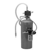
Attaching the
Air Pressure Regulator Assembly
Wrap the threads of the Pressure 1.
Gauge (6) with thread sealer tape.
Screw the Pressure Gauge into the
opening in the face of the Air Pres-
sure Regulator (5). Tighten snugly but
do not over tighten.
Insert the stem of the Air Pressure 2.
Regulator (5) through the opening in
the Bracket (9). Attach the Air Pres-
sure Regulator by tightening the
Compression Nut (22). Press the Air
Pressure Regulator Control Knob
onto the stem.
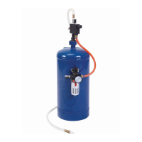
Attach the Air Pressure Regulator 3.
Assembly to the Storage Tank (1).
Place the assembly against the Tank
Bracket (23) and x in place using
two Socket Head Cap Screws (8).
Tighten rmly.
Attaching to Air Compressor
Be sure that the Media Release ON 1.
OFF Valve (18) on top of the Media
Regulator Assembly (15) is in the
OFF position.
Air Hose (10) should be attached to 2.
Air Pressure Regulator (5) outlet and
Media Regulator Assembly (15).
Turn the Bushing (13) that is on the 3.
bottom of the Media Flow Control
Knob (16) onto the Hex Nut (2) that is
on top of the Storage Tank (1). Be-
ing careful to keep the O-Ring (12) in
position, tighten the Bushing (13) until
tight.
Attach the pressure line from the 4.
air compressor (not included) to the
Male Coupler (3).
Open the Air Input ON OFF Valve (4) 5.
at the air pressure inlet.
Adjust the Air Pressure Regulator (5) 6.
to no more than 100 PSI. Read the
pressure on the Pressure Gauge (6),
and adjust by turning the Air Pressure
Regulator Knob (24).
Check to be sure all connections are 7.
tight with no leaks. Disconnect the
air supply and discharge air from
the tank before making any needed
repairs.
Direct the Ceramic Nozzle (21) on 8.
a piece of test material. Open the
Media Release ON OFF Valve (18) of
the Media Regulator Assembly (15).
Adjust the media ow as needed by
turning the Media Flow Control Knob
(16). Turning this knob clockwise in-
creases media ow, counterclockwise
reduces ow.
You can also adjust the impact power 9.
of the media by adjusting the air
pressure. Do this by adjusting the Air
Pressure Regulator Knob (24). Do
not exceed 100 PSI.
Work Piece and Work Area Set Up
Designate a work area that is clean 1.
and well-lit. The work area must not
allow access by children or pets to
prevent injury and distraction.
Route the air hose along a safe route 2.
to reach the work area without creat-
ing a tripping hazard or exposing the
air hose to possible damage. The air
hose must be long enough to reach
the work area with enough extra
length to allow free movement while
working.