Page 13For technical questions, please call 1-800-444-3353.Item 68152
SAFETYOPERATIONMAINTENANCE SETUP
Tool Set Up (continued)
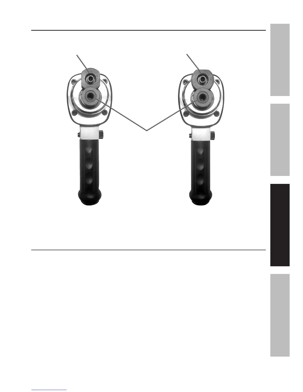
Figure C: Bottom View – Spindle Lock
Spindle Lock
in LOCKED
position
LOCKED
To install
or remove
Backing Pad
UNLOCKED
To operate tool
Spindle Lock
in UNLOCKED
position
Drive
Spindle
Workpiece and Work Area Set Up
1. Designate a work area that is clean
and well-lit. The work area must not
allow access by children or pets to
prevent distraction and injury.
2. Route the air hose along a safe
path to reach the work area without
creating a tripping hazard or exposing
the air hose to possible damage.
The air hose must be long enough
to reach the work area with
enough extra length to allow free
movement while working.
3. Secure loose workpieces using a
vise or clamps (not included) to
prevent movement while working.
4. There must not be hazardous
objects (such as utility lines or
foreign objects) nearby that will
present a hazard while working.