Do you have a question about the Central Pneumatic 34202 and is the answer not in the manual?
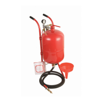
Lists key technical details such as capacity, working pressure, delivery rate, dimensions, and weight.
Advises keeping the manual and invoice for future reference, including assembly, operation, and maintenance.
Covers keeping the area clean, observing conditions, and keeping children away.
Advises not forcing the tool, using the right tool, and proper dressing/personal protection.
Includes warnings on power cord abuse, overreaching, tool maintenance, and unintentional starting.
Emphasizes staying alert, checking damaged parts, using correct parts, and avoiding operation under influence.
Covers draining the compressor daily, ensuring correct pressure ratings, and checking abrasive delivery equipment.
Mandates releasing all air pressure from the tank before opening any part of the system.
Warns against exceeding 125 PSI and details how to safely release excess pressure.
Details the necessary air and sand supply specifications for optimal sandblaster performance.
Instructions for sorting and checking all parts after unpacking the sandblaster unit.
Step-by-step guide for assembling the intake manifold with pressure gauge and valves.
Instructions for connecting the water trap, nipple connectors, and air supply valve.
Steps for assembling the sand control valve with the tank and sand outlet manifold.
Procedure for assembling the nozzle shut off valve, hose adapter, and nozzle.
Connecting the sand hose to the sand control valve and nozzle shut off valve assemblies.
Instructions for attaching the air cap, O-ring, tank cap, and air hose to the main tank.
Steps for attaching the handle bars and handle grips to the sandblaster tank.
Guide for attaching the wheels and foot to the sandblaster unit using cotter pins.
Procedure for screwing the safety valve into the top port of the sandblaster tank.
Detailed steps for loading abrasive media, including safety warnings and fill level recommendations.
Highlights wear-prone components like the sand hose and nozzles, and provides replacement criteria.
A comprehensive list of all parts with item numbers, descriptions, and quantities.
An exploded view diagram illustrating all components and their corresponding item numbers.
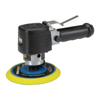
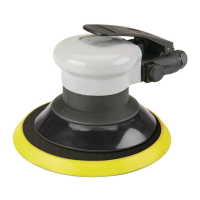
| Speed | 10, 000 RPM |
|---|---|
| Operating Pressure | 90 PSI |
| Hose Size | 3/8 inch |
| Pad Size | 6 inches |
| Air Inlet | 1/4 inch NPT |
| Type | Random Orbital |