ASSEMBLY
NOTE: Use Teflon® Pipe Tape on all threaded joints. Make sure all joints are
securely tighten.
Intake Manifold
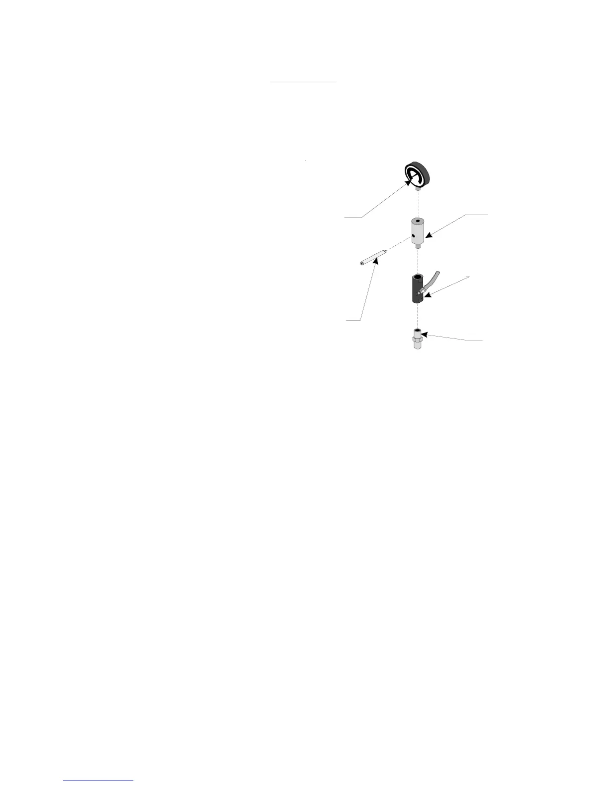
Refer to Figure 1.
Step1: Get out the INTAKE MANIFOLD (#14),
PRESSURE GAUGE (#15), BRASS
THROTTLING VALVE (#18A), 3/8" 1/4"
NIPPLE CONNECTOR (#20), and JOINT
PIPE (#13).
Step2: Attach the PRESSURE GAUGE to the
top of the INTAKE MANIFOLD. Turn
PRESSURE GAUGE so that it’s face is
over the lower side hold of the INTAKE
MANIFOLD.
Step3: Attach the BRASS THROTTLING VALVE to the bottom of the INTAKE MANIFOLD.
Step4: Attach the 3/8" end of the NIPPLE CONNECTOR to the other end of the BRASS
THROTTLING VALVE.
Step5: Attach the JOINT PIPE to the lower side hole of the INTAKE MANIFOLD.
Pressure
Gauge
(#15)
Intake
Manifold
(#14)
Brass
Throttling Valve
(#18A)
Nipple
Connector
(#20)
Joint Pipe
(#13)
Figure 1 — Intake Manifold Assembly
Page #5 -- SKU 34202