Top Assembly
Refer to Figure 6.
Tank
(#1)
Nipple
Connector
(#16)
Nipple
Connector
(#16)
Air Hose
(#21)
Gasket
(#11)
Air Cap
(#12)
Joint Pipe
(#13)
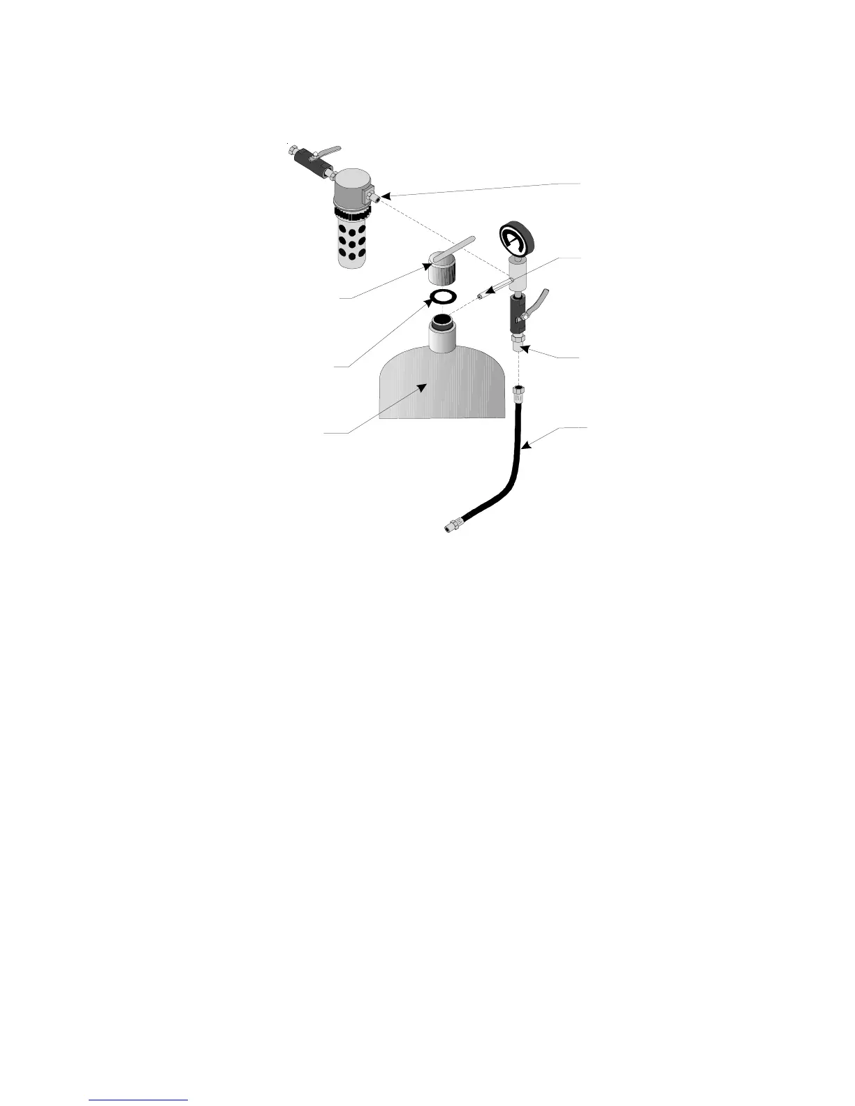
Figure 6 — Top Assembly
Step1: Get the Intake Valve Assembly, the Water Trap Assembly, the Tank Assembly, the TANK
CAP (#12), the O-RING (#11), and the AIR HOSE (#21).
Step2: Attach the Water Trap Assembly’s NIPPLE CONNECTOR (#16) to the upper side
INTAKE MANIFOLD (#14).
Step3: Attach the JOINT PIPE (#13) to the upper side port of the TANK (#1).
Step4: Put the O-RING into the fill port of the TANK.
Step5: Screw the TANK CAP onto the fill port of the TANK.
Step6: Attach the female end of the AIR HOSE to the BRASS THROTTLING VALVE’S (#18A)
NIPPLE CONNECTOR (#16).
Step7: Attach the male end of the AIR HOSE to the SAND OUTLET MANIFOLD(#22),
underneath the TANK.
Page #9 -- SKU 34202