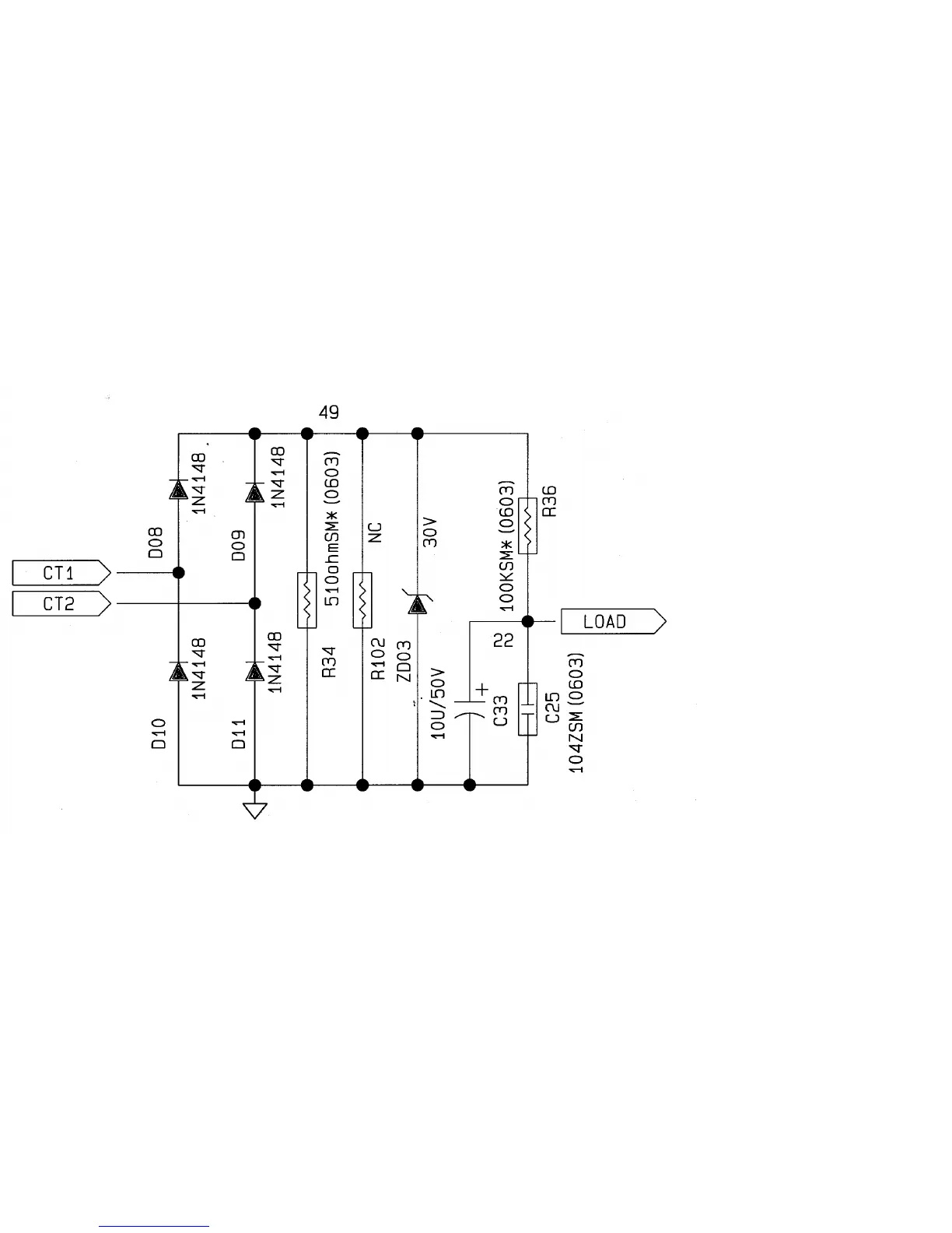
J. Load Detection Circuit
The load detecting circuit is showed on Figure S-9. The output current is sensed by
current transformer CT01. It decrease 1000 times of output current for CPU detection. The
current signal decreased from CT01 pass through a full bridge rectifier and across R36 to get
a voltage signal. After the voltage signal divided by R34,R102 to get 0~5 Volts. signal, the
CPU can get output current value of UPS.
1.
At line/booster/buck mode : The current value multiplies output voltage to get output VA
value.
2.
At battery mode : Because the power factor of square wave is approximately equal 1. The
current value multiplies 120V(230V)output voltage to get output Watt value.
ZD03 is added for protection of rectifier. They can clamp voltage spike while there is a
large current occurs.
Figure S-8 Load Detecting Circuit
26