Generac
®
Power Systems, Inc. 11
Section 3 – Maintenance
CENTURION 3500 Home Standby Generator
• Most lighting, appliance, tool and motor loads indi-
cate their required watts on their nameplate or
data plate. For light bulbs, simply note the wattage
rating of the bulb.
• If a load does not show its rated wattage, multiply
that load’s rated VOLTS times AMPS to obtain
WATTS.
• Induction type motors (such as those that run a
furnace fan, refrigerator, window air conditioner,
etc.) need about 2-1/2 time more watts of power for
starting than for running (for a few seconds during
motor starting). Be sure to allow for this when con-
necting electrical loads to the generator. First, fig-
ure the watts needed to start electric motors in the
system. To that figure, add the running wattages of
other items that will be operated by the generator.
• Do not apply heavy electrical loads for the first two
or three hours of operation.
2.9 PROTECTION SYSTEMS
2.9.1 OVERCRANK — 2 FLASHES OF LED
This feature prevents the generator from damaging
itself when it continually attempts to start and anoth-
er problem, such as no fuel supply, prevents it from
starting. The unit will crank and rest for a preset time
limit. Then, it will stop cranking, and the LED will
light indicating an overcrank failure. The AUTO/OFF/
MANUAL switch will need to be set to OFF and then
back to AUTO to reset the generator control board.
NOTE:
If the fault is not repaired, the overcrank feature
will continue to activate.
2.9.1.1 Approximate Crank Cycle Times
• 15 seconds ON
• 15 seconds OFF
• 7 seconds ON
• 7 seconds OFF
• Repeat for 45 seconds
Approximately 90 seconds total
2.9.2 OVERSPEED — 3 FLASHES OF LED
This feature protects the generator from damage by
shutting it down if it happens to run faster than the
preset limit. This protection also prevents the gener-
ator from supplying an output that could potentially
damage appliances connected to the generator cir-
cuit. Please reference Appendix 1, Troubleshooting, if
this fault occurs.
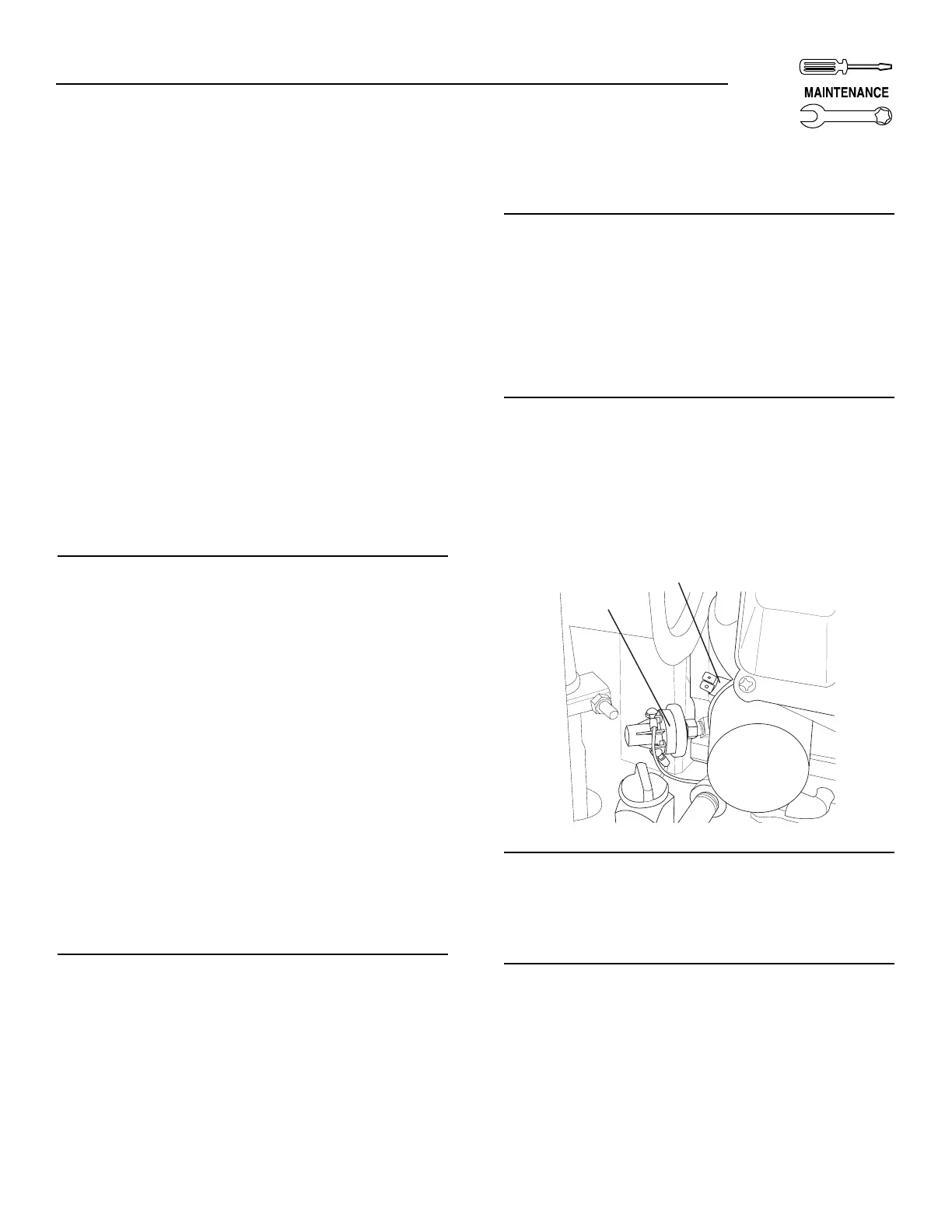
2.3.3 LOW OIL PRESSURE SWITCH —
4 FLASHES OF LED
This switch (Figure 2.2) has normally closed (N.C.)
contacts that are held open by engine oil pressure
during cranking and operating. Should oil pressure
drop below a preset level, switch contacts close, and
the engine automatically shuts down. The unit should
not be restarted until oil is added. Please reference
Appendix 1, Troubleshooting, if this fault occurs.
2.9.4 HIGH TEMPERATURE SWITCH —
5 FLASHES OF LED
This switch (Figure 2.2), which has normally open
(N.O.) contacts, is mounted near the oil filter. The
contacts close if the temperature should exceed
approximately 284° F (140° C), initiating an engine
shutdown. Please reference Appendix 1,
Troubleshooting, if this fault occurs.
Figure 2.3 — Low Oil Pressure and High
Temperature Switches
2.9.5 UNDERSPEED — 6 FLASHES OF LED
This feature protects the generator from damage by
shutting down if it happens to run slower than the
preset limit. Please reference Appendix 1,
Troubleshooting, if this fault occurs.
2.9.6 FIELD BOOST
The Controller Circuit Board houses a field boost
diode and resistor. These two components are part of
a “field boost” circuit (Figure 2.4). During engine
cranking only, a positive DC (battery) voltage is deliv-
ered through the diode, resistor, brushes and slip
rings, to the generator rotor. Application of this volt-
age to the rotor “flashes the field” whenever it is start-
ed. Flashing of the field each time the generator starts
makes sure that a sufficiently strong magnetic field is
available to produce “pickup” voltage in the stator
windings.