Generac
®
Power Systems, Inc. 23
Section 2 – Installation
CENTURION 3500 Home Standby Generator
Figure 2.4 — Feed Power Cord
2.2.3 GENERATOR CONNECTION
The power cord contains five wires with spade termi-
nals. These wires are color coded and and labeled for
accurate connection to the generator’s terminal strip.
NOTE:
Generator mode switch should be placed in the
OFF position. Generator main circuit breakers
should be placed in the OFF or OPEN position by
pulling the reset buttons outward. A visible
GREEN stripe should appear.
1. Remove the four screws that hold the cover plate
in place at rear of generator. Remove cover plate.
2. Remove lock ring from the coupler on end of
power cord. Feed wires through cover plate, Slip
lock ring over wires and reattach lock ring to cou-
pler. Tighten lock ring securely to assure that the
coupler will not loosen during generator opera-
tion.
3. Match the wires by color or by label to the match-
ing terminal positions on the generator. Place the
appropriate spade connectors under the match-
ing terminal screws. (See Figure 2.5). Tighten the
the terminal screws securely to prevent arcing.
4. Align cover plate over threaded holes. Reinstall
and tighten the four screws that hold the cover
plate to back of generator compartment.
Figure 2.5 — Generator Terminal Strip
Connection
2.3 MOUNT POWER TRANSFER
MONITOR
Hold the Power Transfer Monitor in desired location
and mark the mounting holes. The mounting holes
are 1/4 inch in diameter. Drill pilot holes. Use two
fasteners which are appropriate for the area for
mounting the Power Transfer Monitor (Figure 2.6).
NOTE:
If mounting on drywall, it is suggested to use a fas-
tener that spreads behind the hole for added rigid-
ity. This is necessary because of the force that will
be applied when plugging in and unplugging items
from the GFCI outlets.
Figure 2.6 — Mount Power Transfer Monitor
NOTE:
DO NOT plug the six foot sensing cord into stan-
dard household outlet at this time.
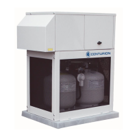
2.4 INSTALL PROPANE TANKS
This generator has been designed for a specific type
of tank. Acceptable tank types are DOT-4BA240 and
DOT-4BW240. Any deviation in tank type may not
allow the tank to fit in the LP enclosure.
Slide the latches on the top of the mesh panel down-
ward. Tilt the panel toward you and lift out The tank
hold down brace is held in place by a large wingnut.
Loosen the wingnut to allow the brace to face per-
pendicular to the opening of the tank enclosure.
Tilt the top of the first tank toward you so the bottom
of the tank enters the compartment first. Set the ring
on the bottom of the tank into the recessed area of
the tank tray. Place tank in upright position in the
tank compartment. Repeat this process for second
tank.
Position tanks so that the tank hold down brace can
be brought down on top of tank flanges and flanges
slip into grooved areas of brace.