24 Generac
®
Power Systems, Inc.
Section 2 – Installation
CENTURION 3500 Home Standby Generator
The changeover regulator needs to be placed at a
height such that the inlet hoses are located even with
or above the cylinder valves on the LP tanks. This will
prevent LP vapor from condensing in the LP
changeover regulator and possibly damaging the fuel
system.
Tighten the wingnut securely to prevent vibration
when the generator is running.
Connect the fuel lines by carefully threading the OPD
(Overflow Protection Device) valves onto the tanks.
Make sure the valve is not cross-threaded which will
cause leaking. Open the valves on both tanks and
swab connections with soapy water to detect any
leaks. Be careful not to crimp the power cord when
the power transfer monitor is in it’s final position.
If a leak is detected in the system near the green swiv-
el connector, there is a possibility that the flare fitting
inside the tank valve has been damaged during the
tank filling process. To inspect the fitting, turn off the
tank valve and visually inspect the flare fitting to
make sure that there are no scratches, dents or mars
on the surface of the flare. If there are visible defects
in the flare fitting of the tank, a new tank must be
used.
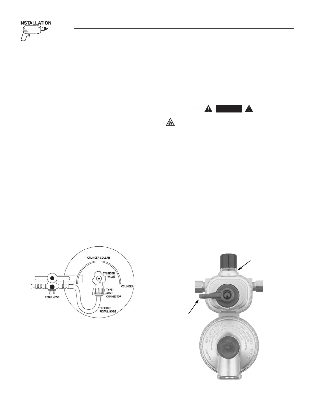
To assure that the hose does not kink, rub against the
tanks or the enclosure, it is important to note the ori-
entation of the valve on the tank. It should always be
pointing towards the front of the cabinet. Do not
allow the hose to kink or rub on the tank (Figure 2.7).
Figure 2.7 — Overhead View of LP Tank
On the propane tank changeover valve, move the
black selector lever to the left or to the right to desig-
nate which tank will be the primary or service cylin-
der (tank). That tank will supply fuel to the generator
first. When the lever is moved to a position an indi-
cator will show green. When that tank empties during
generator operation the indicator will show red sig-
nalling the need to refill the tank. The generator will
start drawing from the reserve cylinder. The
changeover feature allows gives the benefit of unin-
terrupted fuel flow to the generator.
Prior to disconnecting the service cylinder, rotate the
black lever all the way over towards the reserve cylin-
der. (Figure 2.8). DO NOT ATTEMPT TO CHANGE
THE LP TANK WITHOUT ROTATING THIS
LEVER. The full-empty indicator will turn green and
the reserve cylinder becomes the service cylinder.
Refill and reinstall the empty cylinder to maintain
interruption free back up power.
For model 254-00, two-stage changeover regu-
lator, failure to rotate the black lever all the
way over towards the reserve cylinder will
allow propane to leak from the disconnect pig-
tail. Leaking propane, if ignited, will result in a
fire that may cause property damage, bodily
injury or death. REMEMBER: NEVER disconnect
a pigtail if the indicator is RED.
IMPORTANT: Only qualified persons should install,
adjust or service LP ga regulators. If service is need-
ed, contact a qualified LP dealer. Always make sure
cylinders are properly filled and never accept cylin-
ders that are over filled. When replacing newly filled
cylinders to the regulator, check all connections for
leaks with an approved leak detector solution or a
mixture of non-ammonia soap and water. Never use
matches or an open flame.
NOTE:
Low pressure regulators are designed to regulate
LP vapor only.
Figure 2.8 – LP Tank Changeover Valve