Generac
®
Power Systems, Inc. 5
Section 1 – General Information
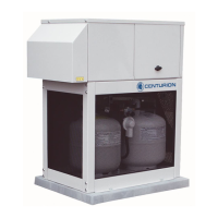
CENTURION 3500 Home Standby Generator
1.1.1 POWER TRANSFER MONITOR
The Power Transfer Monitor controls the automatic
function of the Centurion 3500 generator set. It’s six
foot utility sensing cord monitors the utility line when
it is plugged into a standard household 120 volt out-
let.
NOTE:
Automatic start-up upon utility power outage will
not occur if six foot sensing cord is not plugged
into a utility powered 120 volt outlet.
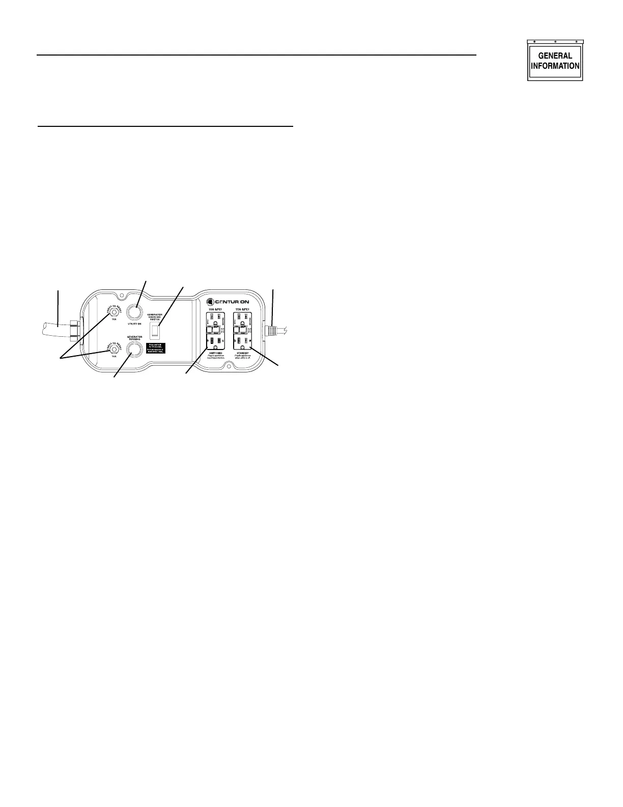
Figure 1.2 — Power Transfer Monitor
1. Generator Power Conduit (15 foot)
2. Circuit Breaker Reset (2)
3. Generator Power Indicator Lamp
4. Utility Power Indicator Lamp
5. Generator Exercise Switch
6. Switched GFCI Outlet
7. Standby GFCI Outlet
8. Utility Sensing Cord (6 foot)
1.1.1.1 Generator Power Conduit
This conduit connects the Power Transfer Monitor,
which is located inside the home, to the generator
outside.
1.1.1.2 Circuit Breaker Reset
If the generator should experience an overload for
any reason, the circuit breaker(s) will trip. The cir-
cuit breaker reset(s) should be pushed to reset after
overload condition has been corrected.
1.1.1.3 Generator Power Indicator Lamp
This lamp will illuminate when the generator has
started and is supplying power to the Power Transfer
Monitor’s GFCI outlets.
1.1.1.4 Utility Power Indicator Lamp
This lamp will be illuminated when normal utility
power is available.
1.1.1.5 Generator Exercise Switch
This switch activates the exercise cycle of the genera-
tor. Make sure the combined loads do not exceed gen-
erator capacity.
1.1.1.6 Switched GFCI Outlet
This outlet is powered by the utility and by the gen-
erator. When utility power is present is acts as anoth-
er normal household outlet. When the generator is
supplying power this outlet is then being supplied
with power from the generator.
NOTE:
There will be a momentary “No Power” period
between the time of utility failure and the genera-
tor start up.
1.1.1.7 Standby GFCI Outlet
This outlet is ONLY powered by the generator. Use it
for additional items during a utility power outage
when the generator is providing backup electricity for
the home.
1.1.1.8 Utility Sensing Cord
When plugged into a standard grounded 120 volt out-
let this cord allows the Power Transfer Monitor to
sense the utility line condition and react to a power
outage.
1.2 UNPACKING/INSPECTION
After unpacking, carefully inspect the contents for
damage.
• This standby generator set has been factory sup-
plied with a weather protective enclosure that is
intended for outdoor installation only.
• This standby generator set is prepackaged with an
automatic power transfer monitor. The power
transfer monitor is prewired with 15 foot conduit
and six foot utility sensing cord with plug. The
Power Transfer Monitor is for indoor installation
only.
If any loss or damage is noted at time of delivery, have
the person(s) making the delivery note all damage on
the freight bill or affix his or her signature under the
consignor’s memo of loss or damage.
If loss or damage is found after delivery, separate the
damaged materials and contact the carrier for claim
procedures if applicable.
Use this generator to supply electrical power for
operating 120-volt, single-phase, 60 Hertz, AC elec-
trical loads. These loads can require up to 3,400
watts (3.4 kW) of power, but cannot exceed 28.3 AC
amperes of current at 120 volts.
✧ ✧ ✧ ✧
✧
✧
✧ ✧
1
2
3
4
5
6
7
8