EasyManua.ls Logo

Ceronix 1505-LCD User Manual

Ceronix 1505-LCD
42 pages
To Next Page IconTo Next Page
Page #1 background imageLoading...
Page #1 background image
CERONIX 15, 17, 19, 20, 22 INCH LCD MONITOR SPECIFICATION AND SERVICE MANUAL 1
15, 17, 19, 20, 22 INCH LCD MONITOR
SPECIFICATION and OPERATION
MANUAL
MODELS
15/17/19/20/2205-LCD
15/17/19/20/2207-LCD
15/17/19/20/2208-LCD
15/17/19/20/2209-LCD
13350 NEW AIRPORT ROAD AUBURN, CA 95602 TEL 530.886.6400 FAX 530.888.1065
WWW.CERONIX.COM
Question and Answer IconNeed help?

Do you have a question about the Ceronix 1505-LCD and is the answer not in the manual?

Ceronix 1505-LCD Specifications

General IconGeneral
BrandCeronix
Model1505-LCD
CategoryMonitor
LanguageEnglish

Summary

Limited Warranty Information

Important Safety Instructions

Operation and Installation Safety

Rules for safe installation and operation to prevent electric shock or damage.

Servicing Safety Precautions

Safety guidelines for servicing the display unit, including power disconnection.

Product Safety Component Identification

Identifies special safety components with a symbol for replacement guidance.

General Monitor Description

General Monitor Features

Native Resolution and Color Specifications

Details native resolutions for different screen sizes and color depth.

Input Connectors and Signal Types

Describes analog RGB (D-Sub) and digital DVI-D input options.

Controls and OSD Menu Functions

Explains OSD navigated keypad controls and menu options for adjustments.

Mechanical Flexibility and Optional Features

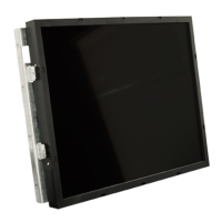
Covers chassis design for mounting and optional touch sensors/remote controls.

Electrical and Panel Specifications

Panel Type and Resolution Specifications

Details panel technology, viewable size, native resolution, and aspect ratios.

Performance Specifications

Covers brightness, contrast ratio, response time, colors, and viewing angles.

Electrical and Connectivity Specifications

Defines interface types, signal frequencies, and power/voltage requirements.

Application Timing and Video Signals

Supported Video Timings Table

Lists resolutions, vertical, horizontal, and pixel frequencies supported by the monitor.

Video Signal Compatibility and Troubleshooting

Discusses VESA compatibility, legacy machine issues, and auto-signal detect.

OSD Image Adjustment and Settings

Guides on using OSD controls (Left/Right, Up/Down, H-Size) to center and fit the image.

Contacting Support for Signal Issues

Information required when contacting support for image shifting or display problems.

Mechanical and Environmental Specifications

Mechanical Dimensions Overview

Details dimensions (W x H x D) for various LCD monitor models.

Environmental Operating Conditions

Specifies operating temperature range and humidity levels for the monitor.

Mechanical Rendering and Views

OSD Navigation and Controls

Basic Adjustments (Contrast, Brightness, Image)

Adjusts contrast, brightness, image position, source, and auto-adjustment.

Advanced OSD Settings (Display, Language, Color)

Covers OSD display time, color, language selection, and factory reset.

Unavailable OSD Functions

Lists OSD functions like Volume, Mute, Auto Dim, and Dimming Range as not available.

Burn-In Mode Operation

A/D Controller Board Overview

A/D Controller Board Connectors

Lists connectors (CN1, CN3, CN4, CN5, CN6, CN8, CN9, CN11) and their functions/pin counts.

A/D Controller Board Pin Descriptions

A/D Controller Board Connector Overview

Lists connectors (CN2-CN15) and their general functions and pin counts.

Power and Control Connector Pinouts

Details pinouts for power input, touch power, GPIO, UART, and inverter control connectors.

Signal Input/Output Connector Pinouts

Details pinouts for LVDS, DVI-D, VGA, and Audio connectors.

Interface and Sensor Connector Pinouts

Details pinouts for OSD Key, IR Receiver, and video signal connectors.

A/D Controller Power Schematics

A/D Controller Scaler Schematics

A/D Controller Interface Schematics

A/D Controller DSUB and DVI Input Schematics

A/D Controller Key Button and IR Receiver Schematics

A/C to D/C Power Supply Unit

A/C to D/C Power Supply Schematic

Circuit diagram for the CPM2201A A/C to D/C power supply unit.

24V 2-Lamp Inverter Module

24V 2-Lamp Inverter DC Supply and Control

Details DC supply, control pins (Bright Adjust, On/Off) for the inverter.

24V 2-Lamp Inverter CCFL Lamp Connection

Specifies connections for CCFL lamp high voltage and return.

24V 2-Lamp Inverter Schematic

Circuit diagram for the CPM2236A 24V 2-lamp inverter module.

24V 4-Lamp Inverter Module

24V 4-Lamp Inverter DC Supply and Control

Details DC supply, control pins (Bright Adjust, On/Off) for the 4-lamp inverter.

24V 4-Lamp Inverter CCFL Lamp Connection

Specifies connections for CCFL lamp high voltage and return on the 4-lamp inverter.

24V 4-Lamp Inverter Schematic

Circuit diagram for the CPM2253A 24V 4-lamp inverter module.

24V 6-Lamp Inverter Module

24V 6-Lamp Inverter DC Supply and Control

Details DC supply, control pins (On/Off, Bright Adjust) for the 6-lamp inverter.

24V 6-Lamp Inverter CCFL Lamp Connection

Specifies connections for CCFL lamp high voltage and return on the 6-lamp inverter.

24V 6-Lamp Inverter Schematic

Circuit diagram for the CPM2469 24V 6-lamp inverter module.

12V 4-Lamp Inverter Module

12V 4-Lamp Inverter DC Supply and Control

Details DC supply, control pins (Bright Adjust, On/Off) for the 12V inverter.

12V 4-Lamp Inverter CCFL Lamp Connection

Specifies connections for CCFL lamp high voltage and return on the 12V inverter.

12V 4-Lamp Inverter Schematic

Circuit diagram for the CPM2237A 12V 4-lamp inverter module.

Related product manuals