YFO-?
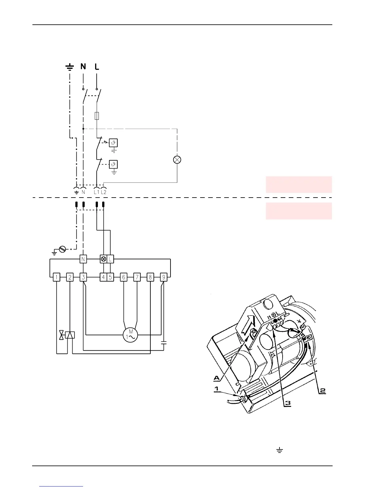
RUN OF THE ELECTRICAL CABLE
1#c# 3&KE"#'E&!G N#c#R"0%*&E
2#c# 3&KE"c7E&5) L#c# M2&$"
3# c#J"*5+!&E#KE(76 c#/0*!"*c"&*%2
Fig. 2
Brown
White (50V)
Blue
=(%(*
3&)&7+%(*
C+5+%#%2"*5($%&%
=&+!#$1+%72
T6A
Black
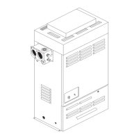
CONTROL BOX
– To remove the control box from the burner,
loosen screw (A, fig. 2) and pull towards the
arrow.
T J2"#)2(%(*"$+$%&!7"#+$#8 +%%"G#G+*"7%E9#+!%(#%2"#7 (!c
%*(E#K(a#P0!G"*!"&%2#%2"#+'!+%+(!c%*&!$8(*5"*Q#(!#&
)E0'c+!#$0))(*%I
230V ~ 50Hz
Y&8"%9#%2"*5($%&%
_"5(%"#E(76c(0%#E&5)
P-,OD#c#OIS`#5&aIQB#+8#*"h0+*"G
Blue
Brown
J"*5+!&E#KE(76#(8
7(!%*(EcK(a#530SE
*
D&E;"
:F-A.
Black
H#)+!#)E0'
H#)(E"#$(76"%
ATTENTION:
Do not swap neutral and phase over, follow the diagram
shown carefully and carry out a good earth connection.
J2"#$"7%+(!#(8#%2"#7(!G07%(*$#50$%#K"#&%#E"&$%#.55kI
(Unless requested otherwise by local standards and legislation).
J2"#"E"7%*+7&E#1+*+!'#7&**+"G#(0%#K9#%2"#+!$%&EE"*#50$%#K"#+!#7(5c
)E+&!7"#1+%2#%2"#*0E"$#+!#8(*7"#+!#%2"#7(0!%*9I
/0*!"*c"&*%2
TESTING
32"76# %2"# $20%cG(1!#(8#%2"#K0*! "*#K9# ()"!+!'
%2"#%2"*5($%&%$I
TO BE DONE BY
THE INSTALLER
CARRIED-OUT
IN THE FACTORY