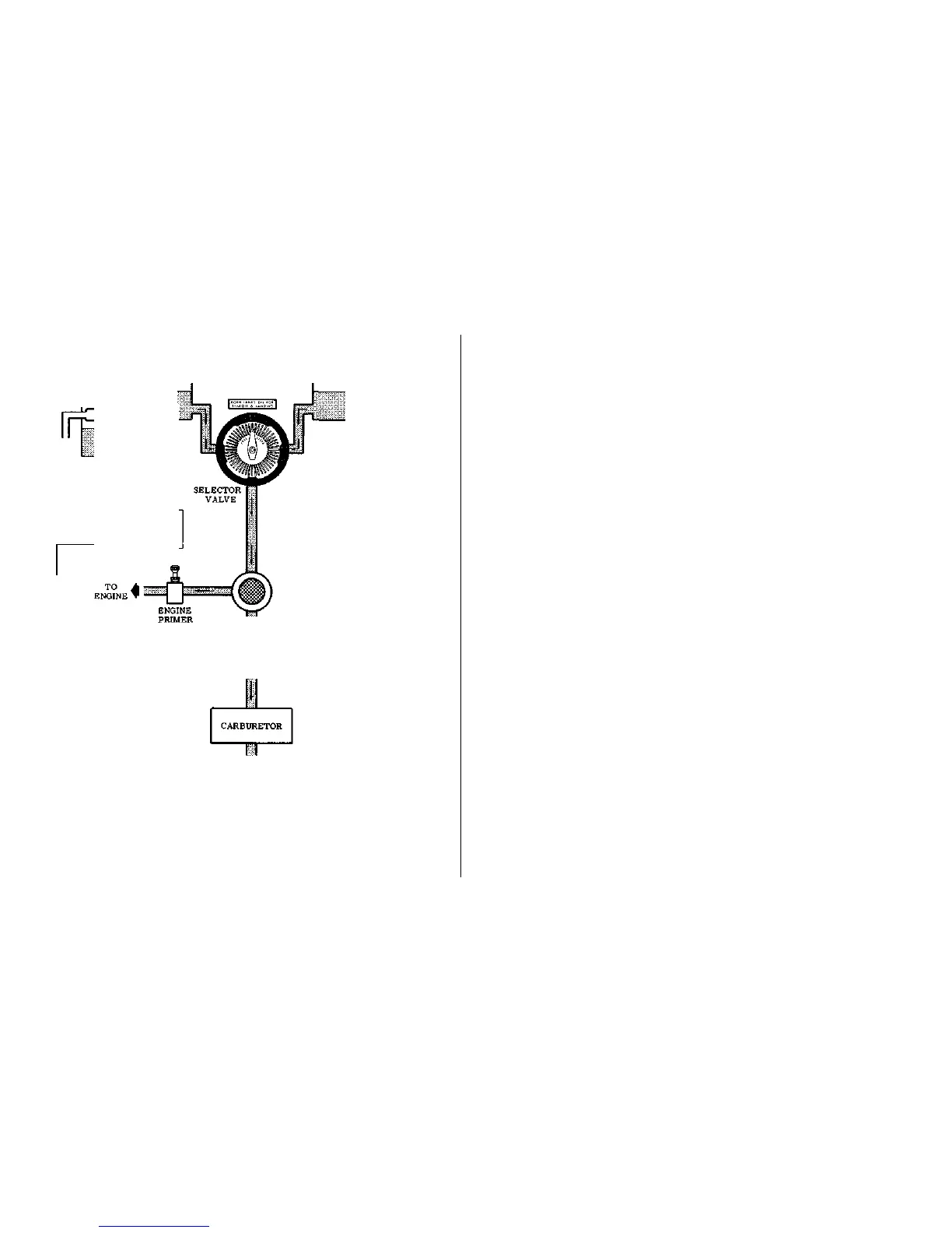
FUEL SYSTEM
SCHEMATIC
RIGHT FUEL TANK
CODE
FUEL SUPPLY VENT
MECHANICAL LINKAGE
M
I
X
T
U
R
E
CONTROL
KNOB
tank may occur if the wings are not maintained exactly level.
Resulting wing heaviness can be alleviated gradually by
turning the selector valve handle to the tank in the "heavy"
wing.
For fuel system servicing information, refer to Lubrication and
Servicing Procedures in Section V.
ELECTRICAL SYSTEM.
Electrical energy is supplied by a 14-volt, direct-current system powered
by an engine-driven alternator (see figure 2-3). A 12- volt battery is located
on the left-hand forward portion of the firewall. Power is supplied to all
electrical circuits through a split bus bar, one side containing electronic
systems and the other side having general electrical systems. Both sides of
the bus are on at all times except when either an external power source is
connected or the ignition/starter switch is turned on; then a power contactor
is automatically activated to open the circuit to the electronic bus. Isolating
the electronic circuits in this manner prevents harmful transient voltages
from damaging the transistors in the electronic equipment.
MASTER SWITCH.
The master switch is a split-rocker type switch labeled "MASTER, " and
is "ON" in the up position and "OFF" in the down position. The right half of
the switch, labeled "BAT," controls all electrical power to the airplane. The
left half, labeled "ALT" controls the alternator.
Normally, both sides of the master switch should be used simultaneously,
however, the "BAT" side of the switch could be turned "ON" separately to
check equipment while on the ground. The "ALT" side of the switch, when
placed in the "OFF" position, removes the alternator from the electrical
system. With this switch in the "OFF" position, the entire electrical load is
placed on the battery, and all non-essential electrical equipment should be
turned off for the remainder of the flight.
AMMETER.
The ammeter indicates the flow of current, in amperes, from the
alternator to the battery or from the battery to the aircraft electrical
system. When the engine is operating and the master switch is "ON, "
2-3

 Loading...