EFFECTIVITY
ALL CFM56 ENGINES
CFMI PROPRIETARY INFORMATION
CFM56-ALL TRAINING MANUAL
BASIC ENGINE
PARTICULARS
BORESCOPE INSPECTION
Page 26
Sep 03
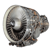
FAN AND BOOSTER
(ALL) :
After entering the air inlet cowl, the total engine airow
passes through fan rotor blades, which form stage 1 of
the low pressure compressor (LPC).
Most of the airow (secondary), is ducted overboard
through Outlet Guide Vanes (OGV’s). The remaining
airow (primary), is directed through a booster, where it
is pressurized.
(-5B, -5C) :
The booster has 4 stages: stage 2 to stage 5.
(-2, -3, -5A, -7B) :
The booster has 3 stages: stage 2 to stage 4.
(ALL) :
The OGV assembly consists of vanes and an inner
shroud. A splitter fairing separates the primary and
secondary airows.
Booster stator.
The stator assembly consists of vanes and inner & outer
shrouds. All vane stages are bolted together.
The shrouds have abradable material, which faces
rotating parts.
Booster spool rotating air seals rub against the inner
shroud, and rotor blades rub against the outer shrouds.
Booster rotor.
The booster rotor consists of a booster spool mounted
on the rear of the fan disk. The blades are installed in
circumferential dovetail slots.
(-5A, -5B, -5C, -7B) :
Each stage has 2 blade locks to ensure the blades are
retained and prevented from rotating in the slot. The
position of the locks is shifted between stages.
Borescope ports.
(-2, -3, -5A, -7B) :
At approx. the 3:30 clock position, there is an unplugged
hole S0, through the OGV inner shroud, at the stage 3
vane assembly.
(-5B, -5C) :
At approx. the 3:30 clock position, there are 2 unplugged
holes, S03 and S05, through the OGV inner shroud.
S03 is located at the stage 3 vane assembly, and S05 at
the stage 5 vane assembly.