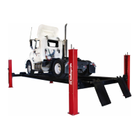
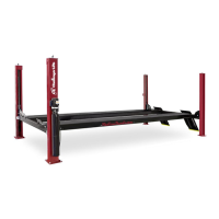
Models 24012 (E, W, EW, XL, LR, AR)
Installation, Operation and Maintenance
File: 24107
7
Rev. 01.09.01
5. Drill the anchor bolt holes perpendicular to the work surface. To assure full
holding power, do no ream the hole or allow the drill to wobble.
6. Drill the hole at least as deep as the full length of the anchor, completely through
the slab if possible.
7. Clean the hole, using compressed air and a wire brush. A clean hole is
necessary for proper performance.
8. Assemble the washer and nut on the anchor bolt so that the anchor protrudes
slightly beyond the nut.
The anchor should drop easily into the hole, requiring no more
than a slight tap to seat it fully.
9. Tap the anchor through the fixture (lift base plate) and into the hole, making sure
that the nut rests solidly against the fixture.
10. Tighten the nut to 150 ft-lbs for 3/4 inch diameter bolts and to 75 ft-lbs for 3/8
inch diameter bolts.
Lift Operation Instructions:
Notice: This Challenger Model 24012* surface mounted automotive lift has been
designed and constructed in accordance with ANSI/ALI B153.1-1990 standard to insure
that it is safe to use. The standard applies to lift owners and employers, as well as to lift
manufacturers. The owner/employer’s responsibilities, as prescribed by ANSI/ALI
B153.1-1990 are summarized below. For the exact wording, refer to the actual
standard included in the literature pack.
The Owner/Employer shall ensure that the lift operators are instructed in the safe use
and operation of the lift using the manufacturer’s instructions and the “Lifting It Right”
and “Safety Tips” literature supplied with the lift.
 Loading...