7 . ACCESSORIES AND OPTIONS
7.66
Challenger MT500B EU
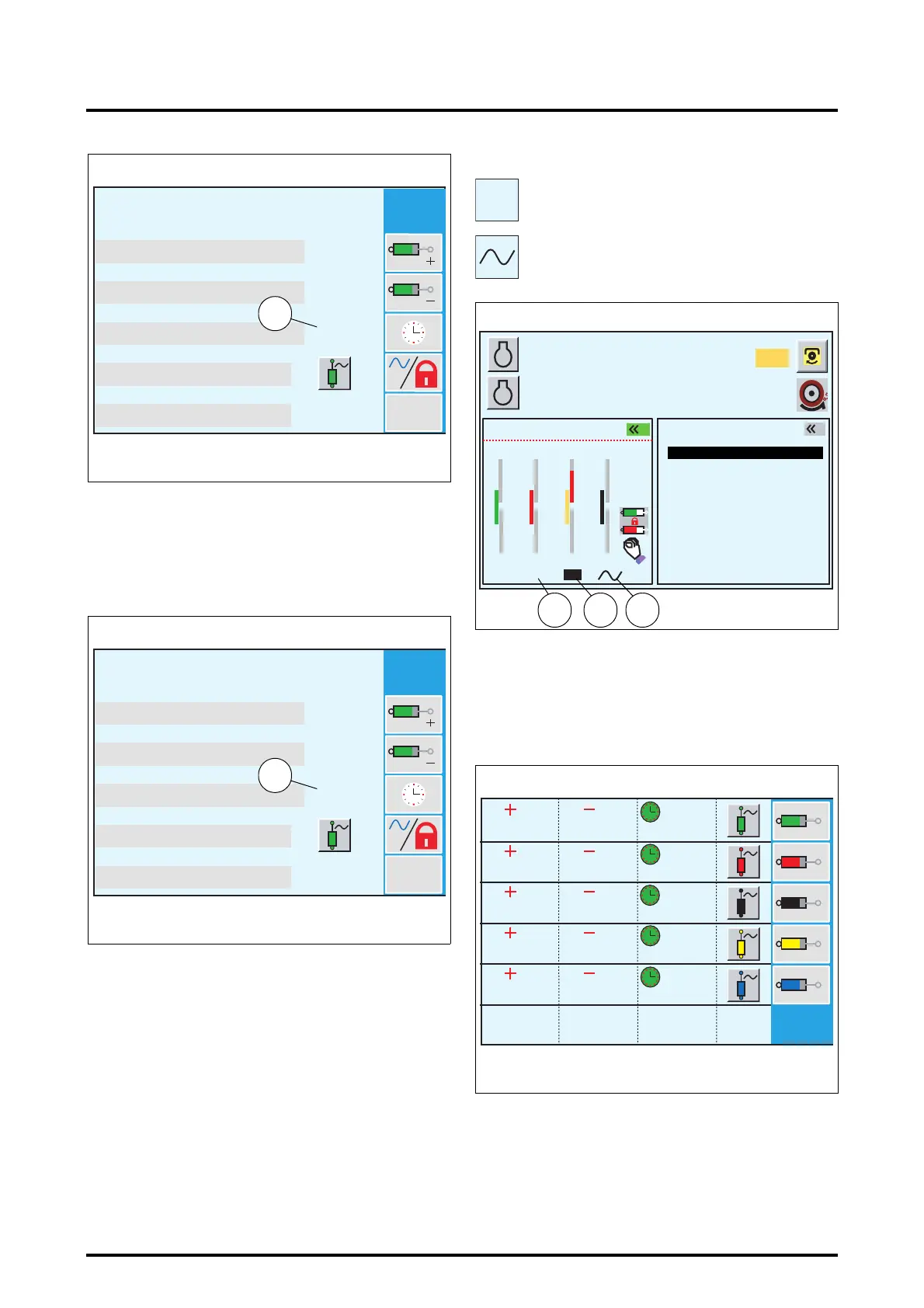
• Adjust the activation time by rotating the encoder (from
0 to 60 seconds or >> for permanent flow (hydraulic
motor supply for example)).
• Validate the value by either pressing the encoder, or by
pressing key «
3
. The value is displayed in black (16 Fig.
148).
To return to the previous window, press the ESC key.
Operation (Fig. 149):
• To initiate a spool valve activation time, push its control
lever beyond 80% of its maximum position, then
release the lever.
• During the activation phase, the time delay set appears
in a black frame (17). As long as the position of control
lever for the concerned spool valve is inferior to 80% of
its maximum position, the generated flow is propor-
tional to its position. Beyond 80%, the flow generated is
that which was stored.
• Two other different symbols can be displayed depend-
ing on the configuration:
NOTE: To display this window, see section 7.3 (WORK
application).
7.12.3.3 - Activating the floating position (Fig. 150)
• Select the spool valve to adjust using keys
«
1
to «
5
.
Example: key
«
1
provides access to the first spool valve. A
new window is displayed (Fig. 151).
100%
100%
0s
Reset
0s
0 < . . < 100%
0 < . . < 100%
0 < . . < 60s / >>
100%-0s-FLOAT=OK
FLOAT : OK-KO
Z3A-888-08-04
Fig. 147
15
100%
100%
0s
Reset
8s
0 < . . < 100%
0 < . . < 100%
0 < . . < 60s / >>
100%-0s-FLOAT=OK
FLOAT : OK-KO
Z3A-889-08-04
Fig. 148
16
Permanent spool valve flow (18)
Spool valve in floating position (19)
>>
A
B
1000
2000
790
5.3
10% M
5%
540
1
2
87
89
76
28
100
19
9853
2s
5 s
>>
Z3A-890-08-04
Fig. 149
GEARBOX SETTINGS
ACTIVE MEMORY
HEADLAND
POINTS
EHS VALVES
RPM
KPH
EHS VALVES
191718
100%
100%
100%
100%
100%
100%
100%
100%
100%
100%
0s
0s
0s
0s
0s
Z3A-876-08-04
Fig. 150
 Loading...