7 . ACCESSORIES AND OPTIONS
7.86
Challenger MT500B EU
During use, a symbol is displayed below the lift ram to indi-
cate the linkage control position (examples 72 Fig. 209).
The following symbols can be displayed:
To return to the window (Fig. 205), press the key
«
5
when
the window (Fig. 209) is open and the icon (71 Fig. 209) is
green.
NOTE: On a b/w display, the active window is indicated
by the same icon in reverse video.
7.14.0.4 - Working operation
To activate disc tiller Lifting or Lowering, use the rear link-
age control. When the TIC is in use, the linkage is inactive
and locked.
As soon as the implement is in working position, wheel
slip, implement depth and the draft applied to the lift arms
(if the implement is hitched to the lift arms) are analysed by
the calculator, which varies the implement working height
accordingly.
IMPORTANT: If the disc tiller high and low position
stops are modified during work, they are not stored in
the DATATRONIC active memory. To memorise them,
see paragraph 7.8.4.2. (Memorising the disc tiller high
and low positions).
Displaying parameters:
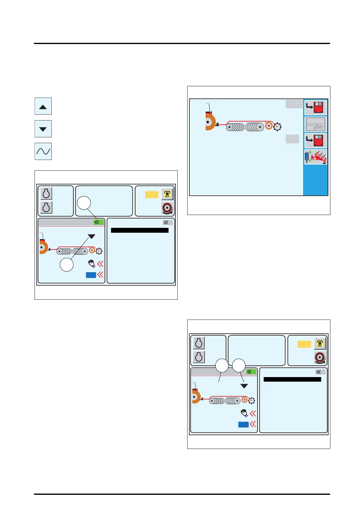
During work either the Settings window (Fig. 210), or the
Work window (Fig. 211) can be displayed.
Description (Fig. 210):
As the disc tiller position changes, the high and low posi-
tion values vary accordingly in the white boxes.
The values in the grey boxes are memorised and hence
fixed.
Description (Fig. 211):
To display this window, press the key
«
3
when the win-
dow (Fig. 210) is open.
Left-hand part of the window:
73. Active disc tiller position value.
74. Indicate the spool valve control status.
Linkage control in raised position
Linkage control in lowered position
Linkage control in floating position
A
B
1000
2000
790
5.3
10% M
5%
540
2
2000
23 %
1
ON
Z3A-1320-11-04-B
Fig. 209
RPM
KPH
72
71
GEARBOX SETTINGS
ACTIVE MEMORY
HEADLAND
POINTS
EHS VALVES 5-6
EHS VALVES 1-4
TIC
85%
22%
22%
85%
1920
42.0
Z3A-990-08-04-B
Fig. 210
A
B
1000
2000
790
5.3
10% M
5%
540
2
2000
23 %
1
ON
Z3A-1320-11-04-B
Fig. 211
RPM
KPH
TIC
73 74
GEARBOX SETTINGS
ACTIVE MEMORY
HEADLAND
POINTS
EHS VALVES 5-6
EHS VALVES 1-4
 Loading...