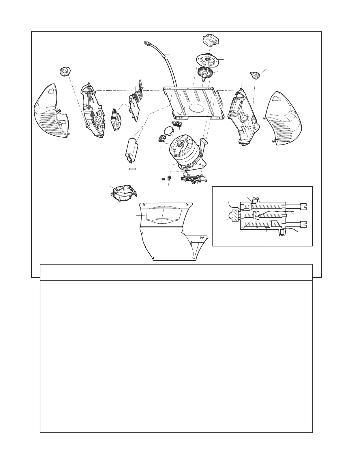
KEY PART
NO. NO. DESCRIPTION
1 41A4371 Belt Cap
2 41A4885-5 Gear and sprocket assembly
Complete with: Spring washer,
thrust washer, retaining ring,
bearing plate, roll pins (2), drive
gear and worm gear, helical gear
w/retainer and grease
3 41A2817 Drive/worm gear kit w/grease,
roll pins (2)
4 41B4245-1 Line cord
5 41A5484 End panels w/all labels
6 4A1344 Light socket
7 108D79 Lens
8A 30B530 Capacitor 56uF
8B 30B529 Capacitor 40uF
8C 41A5637 Resistor
9 41A3150 Terminal block w/screws
10 41D5563-1 Universal replacement motor &
bracket assembly
Complete with: Motor, worm,
bracket, gear case, bearing
assembly, RPM sensor
KEY PART
NO. NO. DESCRIPTION
11 41A5633-12 Cover
12 41A2818 Limit switch drive & retainer
13 41D3452 Limit switch assembly
14 41A5532 Gear case
15 41A2822-1 Interrupter cup assembly
16 41C4398A RPM sensor assembly
17 41AB075-2 Receiver logic board assy.
Complete with: Logic board,
end panel w/all labels, light
socket
18 41C5588 High voltage wire harness assy.
41C5587 Low voltage wire harness assy.
19 41D180-1 End panel w/all labels
NOT SHOWN
41A2826 Motor shaft bearing kit
41A2825 Opener assembly hardware kit
(includes screws not designated
by a number in illustration)